 Part of my plan for Mound City 1862 is to have authentic looking track work. That will mean rough wood ties, stub switches and code 55 track. Essentially I have to hand lay all of the track.
I have never hand laid track before, much less a turnout. So I am delving into it one step at a time. The Mound City Railroad laid the original track and there is very little information on materials used and ties per mile. As a result I will use the Illinois Central standards as the basis (although there is little info there too). By 1862 the IC was more or less operating over the line (there are conflicting accounts on when it was taken over). My assumptions will be that since this is a branch the tie spacing will be wider but the sleepers will be mostly mass produced and square. This is a time before creosote was used so they will need to be weathered as if raw wood was in the elements for a few years.
I picked up some weathered code 55 Micro Engineering rail and basswood 1/8 x 1/16 (approximates a 10 x 6 sleeper) and set about experimenting. With the small layout I decided to go with #5 turnouts. I did a quick test with a straight piece of track on some wood ties just to get a feel for using the gauges. I also wanted to test spiking through ties. I am using the very small Micro Engineering spikes. I learned that pushing the spikes through the basswood does not work. I will have to pre-drill all the spikes. After some trial and error I figured out the best technique for me was to use small dabs of CA, lay the track piece and then spike after. The CA holds strong enough for the drilling and spiking.
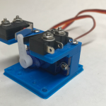
I would have purchased a jig and other tools from Fasttracks if I could have afforded it. The biggest unknown for me was how to go about making the frog for the turnout. I decided to make a jig so I could file and solder them together. I used a scrap piece of plywood as a base. I cut two small pieces of plastic shower board scrap at 5.5 degrees (1/2 the total 11 degrees). the plastic board is exactly the same thickness as the height of the rail. I then filed a 45 degree angle on the edge that sits against the rail. This allowed the rail to slide underneath and have the head flush with the top of the plastic board. I glued them to the scrap board so that they held the rail at a 5.5 degree angle to the edge of the board. I could then slide the rail in and file it to the correct angle.


On the same scrap board, I added some strip wood and some more plastic scrap cut at 11 degrees. This formed a soldering jig for the frog. I left the plastic pieces loose so that it can be pulled away and release the frog. The blue dots in the images are from where I started to glue these down and then realized I would not be able to get the frog loose if i left it that way.

One additional step I added (after the first one I made) is to add a small piece of wire to the back of the frog when I solder it. this is to power the frog. It is much easier to do now than later on the layout.
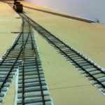
Once I felt comfortable about the frog I tried laying the ties on the a template. I downloaded a #5 template from Central Valley Model Works. Since this is a stub turnout I laid all the ties up to where the points would start. I used CA to glue each tie to the template. Then I glued the frog into position, using the lines on the template as a guide. I then cut each piece of rail and used CA to attached them to the ties. Before bending the wing rails I notched the bottom of the rail so it would bend easier. I used an NMRA gauge and a 3-point gauge to make sure the track was in gauge as I went. The rail position on the template helps but you must check gauge as you go.

I read a lot of how-to articles on making turnouts before I attempted this. The one item I took literally is that the first turnout will not be good. I was very pleased with my first turnout but I could see where improvement was required. The biggest problem with this first turnout was the guard rails. They were too far from the outside rail allowing the flanges to catch the frog. This was easily corrected on my later efforts.
I now felt confident to proceed with the rest of the track laying. To space the ties correctly I made another jig by using my radial arm saw to cut slots in a scrap of plywood. the idea was to lay all the ties in the jig, use tape to lift them and then place them on the layout. I did a test first on a scrap of wood to see how this would work. The results looked very good, if I was modeling a modern era!

I decided instead to use the same technique I had used on the turnouts. I downloaded the branch line track template from Central Valley Model Works. The branch line template has wider tie spacing that I felt would be more appropriate. I used Adobe Illustrator to import the PDF file and did a full size drawing of the track plan. This allowed me to print the plan and tape it down to my bench work for a full size mock-up. When I had finished taping it down, I found that adjustments were required. This system made it easy to go back to the computer, make the adjustments and print a new layout.

I cut the track template out and pasted it directly to the layout. This gave me the tie spacing and tie size for every bit of the layout. I then built the three turnouts in place on the templates just like I had done my test turnout.

I should mention at this point how I made the ties. I did not purchase pre-cut ties. Since I was modeling 1862, I wanted the ties to be a little rough. I used 1/8 x 1/16 basswood strip. I pre-painted all the wood before cutting it. I used a variety of colors to get a varied look between the ties. According to history the original ties were laid about 7-8 years prior to the time I am modeling Since there was no creosote back then the ties would look bleached from the weather and blackened by ash, oil and other residues. I am assuming that some ties would have been replaced and the color would not be consistent. To get the varied weathered look, I used several colors of artist water based paints with a black wash. I would lay all the colors out and each time I went back for some paint I would vary what I used. I also did not paint on any full color. I would dry brush or use extra water to thin the paint to a wash. Again each brush was different. After painting, I cut the ties to length.

The ties were glued to the templates using CA. This went very quickly as I would do 10 at a time. The template showed me exactly where to add beads of glue as I went. The slight variations in the ties from my fat fingers provided the variation of early railroading I was after. Before laying rail, I lightly sanded the tops of the ties to catch any high spots (did not want to ruin that paint on the ties). Once the ties were down I used CA to glue the rail in place.


That is as far as I have progressed so far. I still need to spike everything, gap the frogs, add jumper wires and ballast. I will also be painting on a final wash of black to the ties to color the ends and cover up any other imperfections. So far I am happy with the results.
One addition to this article, all the paper templates were glued down to the foam with LOCTITE® POWER GRAB® construction adhesive. I have found this stuff works so well, I use it on all foam based projects. I even use it for laying track on wood.
Marshall, very nice work! I really like nyour blog, to sad that ist stopped somewhere. Is there some progress and are you still with us? hope to hear 😉
Grtz, Ronald from the Netherlands.
Hello Ronald,
Thank you for the kind words! I have not gone away for ever, but do have my hands full on several duties with the NMRA and writing an article for a major magazine here. I will be back, as I do love writing about all the railroad history, small layouts, and modeling.
Like the fact that you are not using PC Board to hold everything together… all wood ties look much better. I did several searches through YouTube and all are using PC Board and most use one of the commercial turnout fixtures. I finally searched my old Model Railroader Magazines and came across the article “Building a turnout from scratch” by Tony Koester, December 1989 – 10 pages of great instructions accompanied by detailed photos and illustrations. Although he did not use CA glue and only spiked his rail to the ties… my thought were to use CA even before reading your article. The only place Tony use PC Board and soldered to rails was the Turnout Rod. I’m not seeing what you used for your Turnout Rod???
I did these turnouts so long ago, I had to pull the layout and check how I did them. These are stub turnouts! It appears I used a shorted piece of rail joiner soldered to a PC board tie and the rail rides in the joiner. It is allowed to be loose so as not to bind the throw. The throw length is limited by a piece of wire imbedded in the adjacent ties to limit the action. Its been a number of years and they still work very well.
Yes in some instances Old School can be so much better. I’m still working on how I might do the Turnout Rod… just received some information from fellow modelers on photos of the Colorado & Southern of their Turnout Rods and will base my modeling on that. I’ve keep a note to let you know what I come up with.