
The design for the layout included the need for a traverser so trains appear to go somewhere. I am hoping to stage up to three trains for a mix of operations.
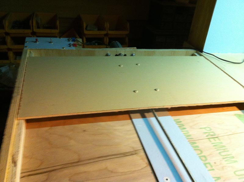
To build the traverser, I used 1/4″ underlayment (thin smooth plywood) as the bottom. This was placed directly on the frame of the module. I then used 1/2″ plywood ripped to 1 1/4″ as the frame. I then added extra lengths of 1/2″ plywood ripped to 1″ at the edges for the traverser table to ride on. The table is made from the same underlayment as the bottom. The blue material is a scrap piece of vinyl from a bathroom project. It provides a smooth surface for the mechanism to slide upon.
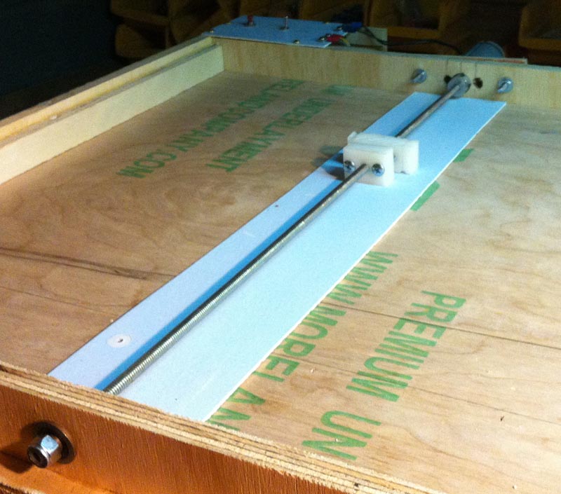
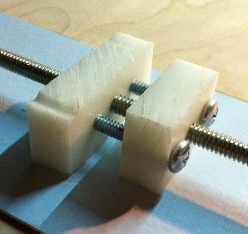
The idea for the mechanics of the traverser came from a JGRO CNC Router project I had built. The plans and specs for the router are at http://www.cncroutersource.com/cnc-router-plans.html. The threaded road and Delrin material came from this project. The Delrin is drilled and tapped to accept the rod. As the motor turns the shaft, the travels along the shaft. The traverser table has two pieces of wood slotted to accept the Delrin. Delrin is used because it has natural properties that lubricate the shaft for smooth operation.
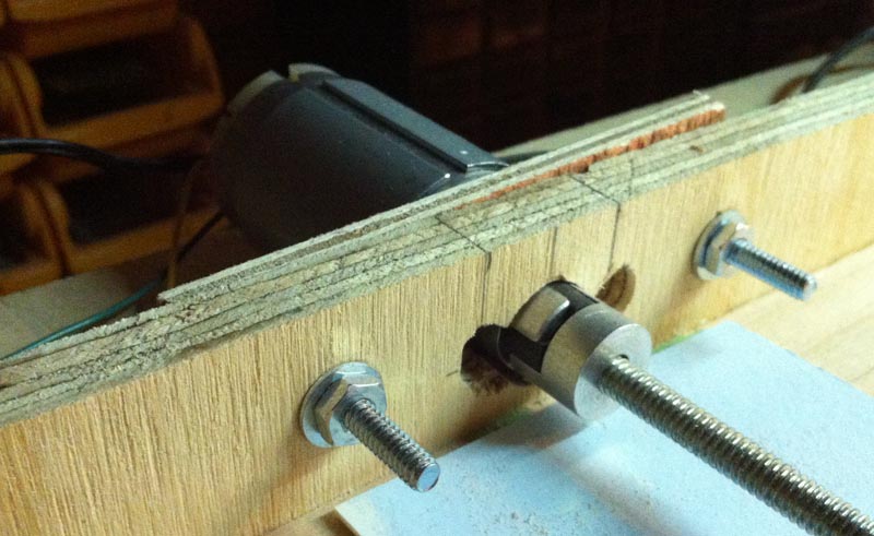
The other parts of the mechanism are left over materials I had from other projects. The motor is from an old printer that my work was throwing out. I have found the same motor in cordless screwdrivers. The threaded shaft and other hardware can be purchased from any hardware. The couplings can be found at many robotics parts sources on the internet.
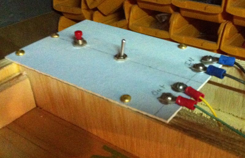
The electrical is a simple push button switch and DPDT switch to reverse polarity. It is wired the same way as a analog DC layout direction switch. this setup allows me to control the direction of the table and the table only moves when the button is held down. Power is supplied by a 7 volt DC wall wart. I used more of the left over vinyl for panel.
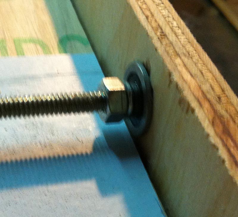
Of great importance is the end bearing assemblies. These hold the rod at the correct height and if adjusted correctly keep the table from bouncing. The bearings were purchased from McMaster-Carr. I used vinyl nuts to keep them from “walking” down the rod as it turned. They are lightly nudged against the bearings to keep everything in place. Tighten too much and the rod will bind, too loose and it will bounce.
The table is cut from a piece of 1/4″ plywood underlayment. On the underside I placed two peices of 3/4″ particle board. the particle board is drilled and tapped to accept the bolts and wheel assembly. The wheels are roller skate bearings I took out of some old skates that did not fit my kids anymore. The table will ride on these creating a smoother mechanism. This was another idea that came from the JGRO CNC Machine.
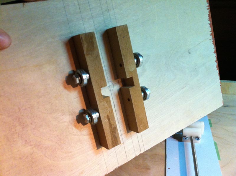
The table simply straddles the Delrin and moves with it as it moves down the shaft.
Video of the traverser in action can be seen at http://youtu.be/2GvYP4fFyAA and http://youtu.be/ZzLnmGdPC0g.
could you please supply a cutting list for this project? I want to build something similar, but without
the electric motor as a manual one will suffice.
I am sorry but I will not be able to supply it. This article is a bit old and I have since removed the traverser. To be honest, over time I found this design to not work the greatest. I had issues with it binding and the motor was not smooth enough creating derailments. I am planning on installing a manual pivot table but have not finalized the design yet.
i shall be interested to see what you come up with