
When I design modules, I always try to make them a single element with everything required for setup in one package. The trains themselves must be transported separately for obvious reasons but things like legs, scenery and some structures in my mind can all be together as a single unit which can be picked up, moved and unpacked easily at show time. On Free-mo modules, I believe I have perfected this to some extent with my integral leg and cart design.
I am now looking to extend that thinking to small layout designs for table top display. I have seen others create a “coffin” for a layout which covers the layout during transport and while in storage. This method appears to work fine in most situations but has the following drawbacks:
- Locating a place to store the coffin during a show can be a problem
- The coffin is usually larger than the layout
- The coffin adds to the weight of the layout during transport
- Placing the coffin on/off the layout can cause damage
- Securing the coffin to the layout can be cumbersome
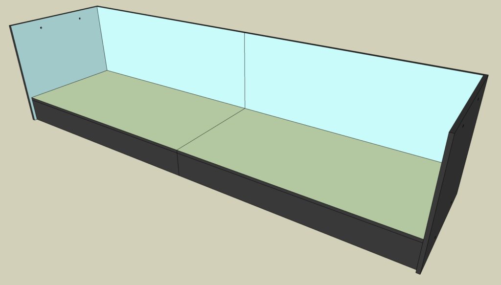
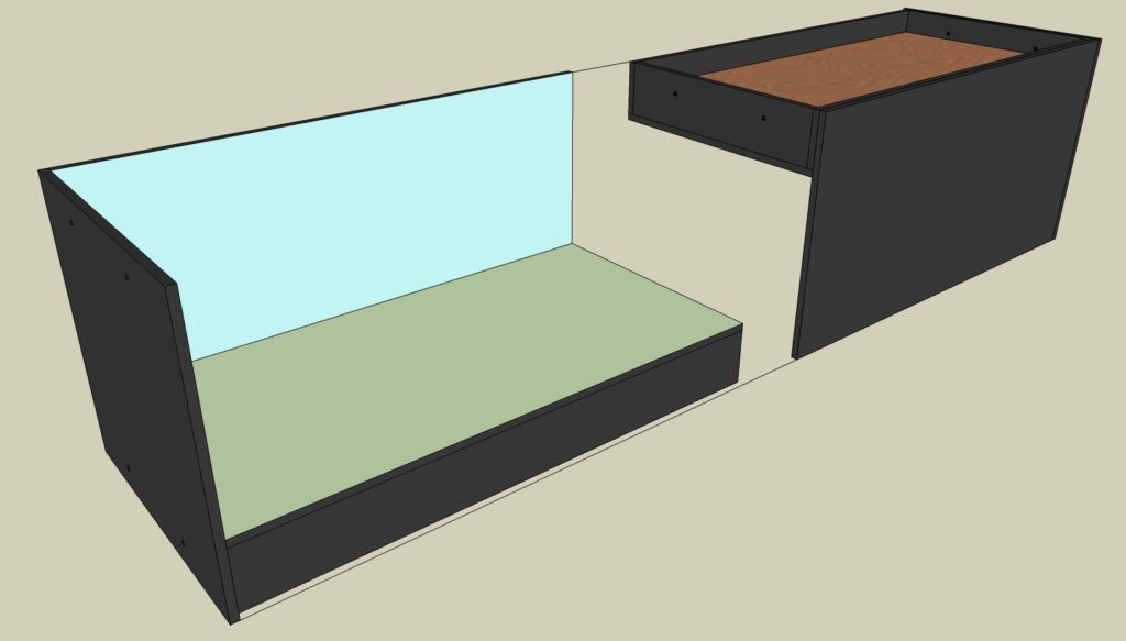
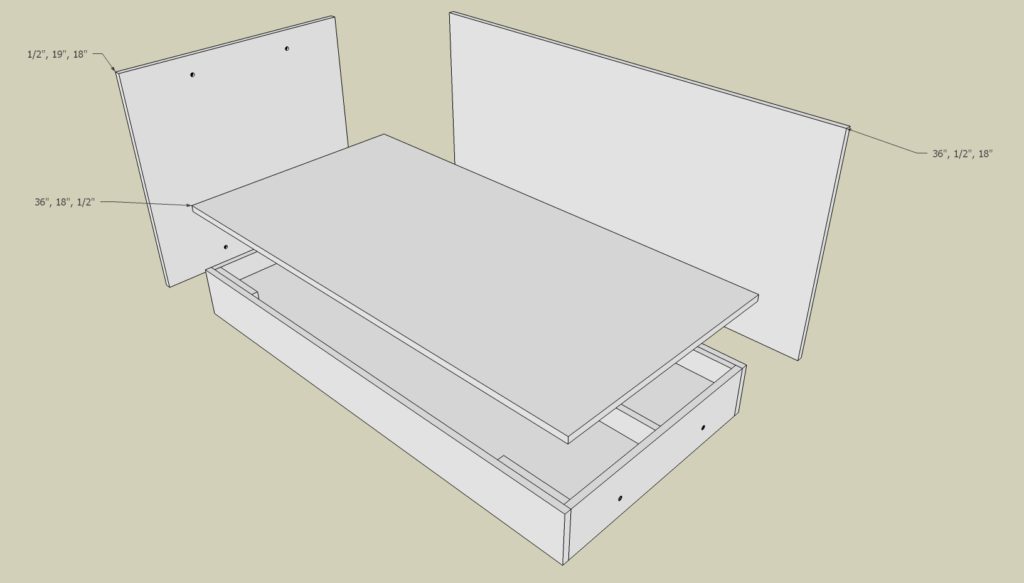
I had been contemplating for some time that a layout which folds up upon itself may help to alleviate some of these disadvantages. The frame of such a layout will need to be built of more robust materials than just foam core but not too heavy and make the layout difficult to transport. My idea for a folding layout centers around the idea that the layout will split into two halves and then they should fit back together, opposite of each other creating a box.
My design is for a 72″ X 18″ layout (73″ x 19″ exterior dimension) which folds up into a 37″ x 19″ x 18″ box. The box will have four bolt locations to secure the box for transport.
When setup for display on a table top, two bolts are used to securely hold the two halves together. If someone decides to use this design on anything other than a table top, a more secure system will be required.
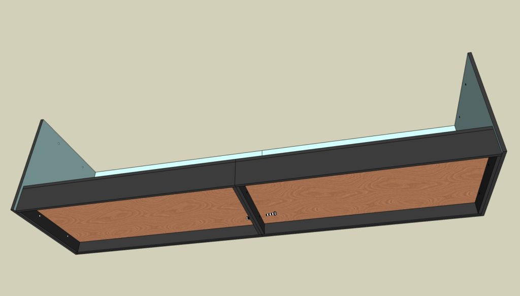
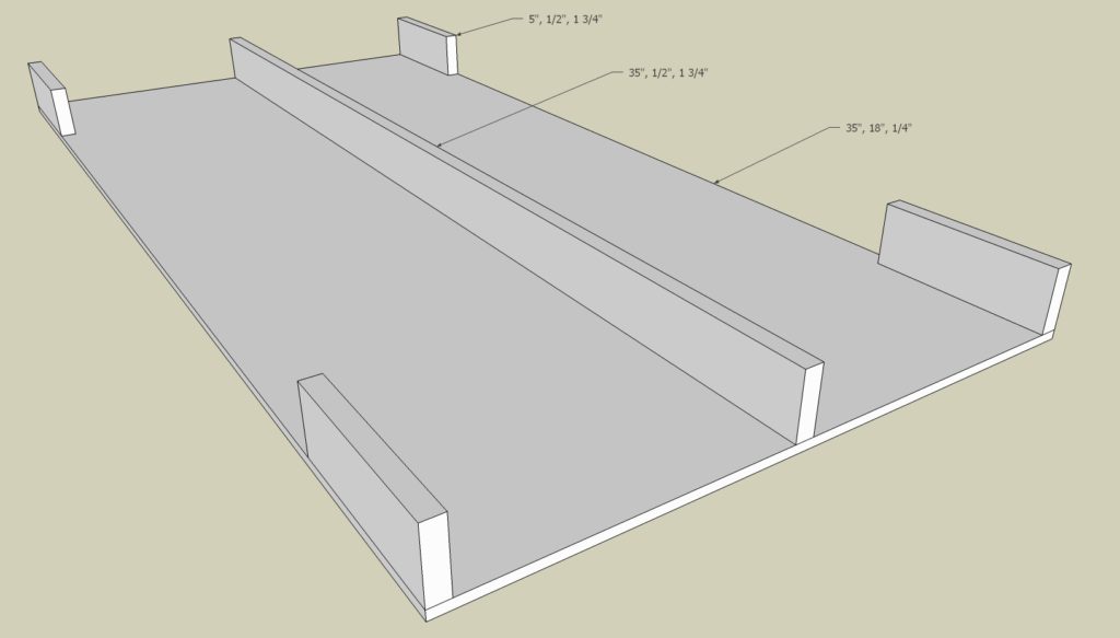
To hide any wiring when in the box configuration, a 2″ pocket was created using plywood spacers and a piece of 1/4″ Lauan.
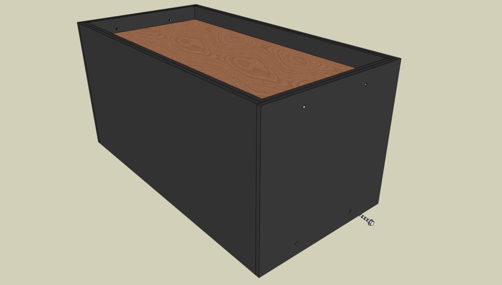
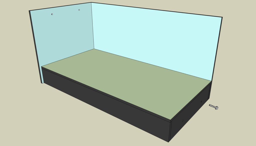
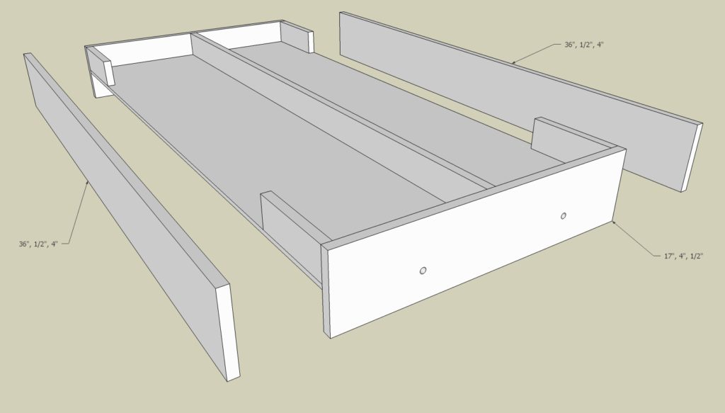
The construction calls for 1/2″ birch plywood except for the underside pocket (to hide the wiring) which is capped by a piece of 1/4″ Lauan. The base is constructed from four pieces of 1/2″ birch plywood to create the two 36″ X 18″ halves. These base sections are 4″ deep.
All portions of the construction should be nailed and glued except the Lauan bottom. This needs to be secured with screws to allow access for future maintenance. I am sure to do some test builds of this concept in the future and will share the results here. Some enhancements I am already contemplating include:
- Adding holes to the cross member in the wiring cavity
- Adding a port for electrical connections
- Adding handles or some other means for a single person to pick up the box
- Adjust the number of bolts used for the box to be equal to the number of bolts in layout mode
- Add an additional anchor point to the backgrounds in display mode to keep them in line
So the next big question is, if I build the box, what layout will I put in it? I welcome plan ideas from any readers!! The final dimensions are 72″ X 18″. Cutting a hole and adding a fiddle track is possible with this design but I would request the track have the ability to be stored with the box and the hold be covered some way when in transit.
Note: scenery elements may not have a height of greater than 9.5″ (about 68 scale feet in HO) in the current configuration. This can be altered by increasing the height of the back and side boards. Tall scenery elements must also not be located where they will interfere with scenery elements on the opposite end of the layout. This will create some design challenges.
Cool!
I like where this is headed. Further, installing two sides of the backdrop on each module will help carry any transverse loads placed on the box while in transit. Maybe a little extra bracing in that corner to help?
The tray created in the base of the layout for wiring: could it be made deeper?
If it was you could possibly store two additional, shallow, staging wings in there to facilitate either staging or to extend the railway on either side, off-stage if that helps the planning process.
You really could store rolling stock and even tools in the bases too. This way all the railway stuff could be retained in the one envelope. Perhaps using a sort of nested tray like the ones from inside a toolbox (the example not literally using one). Doing so might help keep everything tidy but if this was being built for a show then keeping everything in the same volume might help it ensure nothing gets left behind on the way to or from the show.
I’m looking forward to seeing where this goes.
Chris
Chris,
I agree with most of your thoughts. The base could be easily increased for additional storage. The design will allow for additional bracing but since I am not an engineer i am not sure how much more may be required. If/when I build a sample, I will test the limits.
Thank you for the great thoughts!!
Dear Marshall,
Foamcore is more than capable of performing in such a design,..
…come to think of it, I think I’ve seen something like this before… http://www.zelmeroz.com/album_model/members/klyzlr/Camp4.pdf
Happy modelling,
Aim to Improve,
Prof Klyzlr
I had forgotten about Camp 4, thank you for sharing! Camp 4 is a bit smaller (designed for air travel) but the concept is very similar with each half fitting over the other.
i agree, foam core is an option!
As the Prof said “Foamcore!”… I am designing (in my head ) a new small layout for my desk… 2 – 2’x4′ sections. This idea will fit perfectly. I was thinking how high to make my base. Thanks Marshall for the dimensions. I will creating an N Scale layout. I would still make the base a thin wood structure and the backdrops Luan (12” high).. In this way the ‘box’ is of a stronger wood structure for storage. The deck would be thick foamcore as well as the supports. If the management desires it then could be stored or relocated…. (Dining Room hi hi). I could also relocate this to the attic easily… A 2’x4’x2′ box would be easily moved around.
Prof… I have retired and moved from NJ to North Carolina since listening to you on Model Rail Radio podcasts. Presently I am measuring (over time) the affects of temp on the linear expansion of track. I have lengths of HO and N scale track mounted on wood. Measuring the metal rail lengths for expansion. My attic can go anywhere from 30-110 degrees F. Still trying to find out if anyone has had any experience in dealing with this issue.