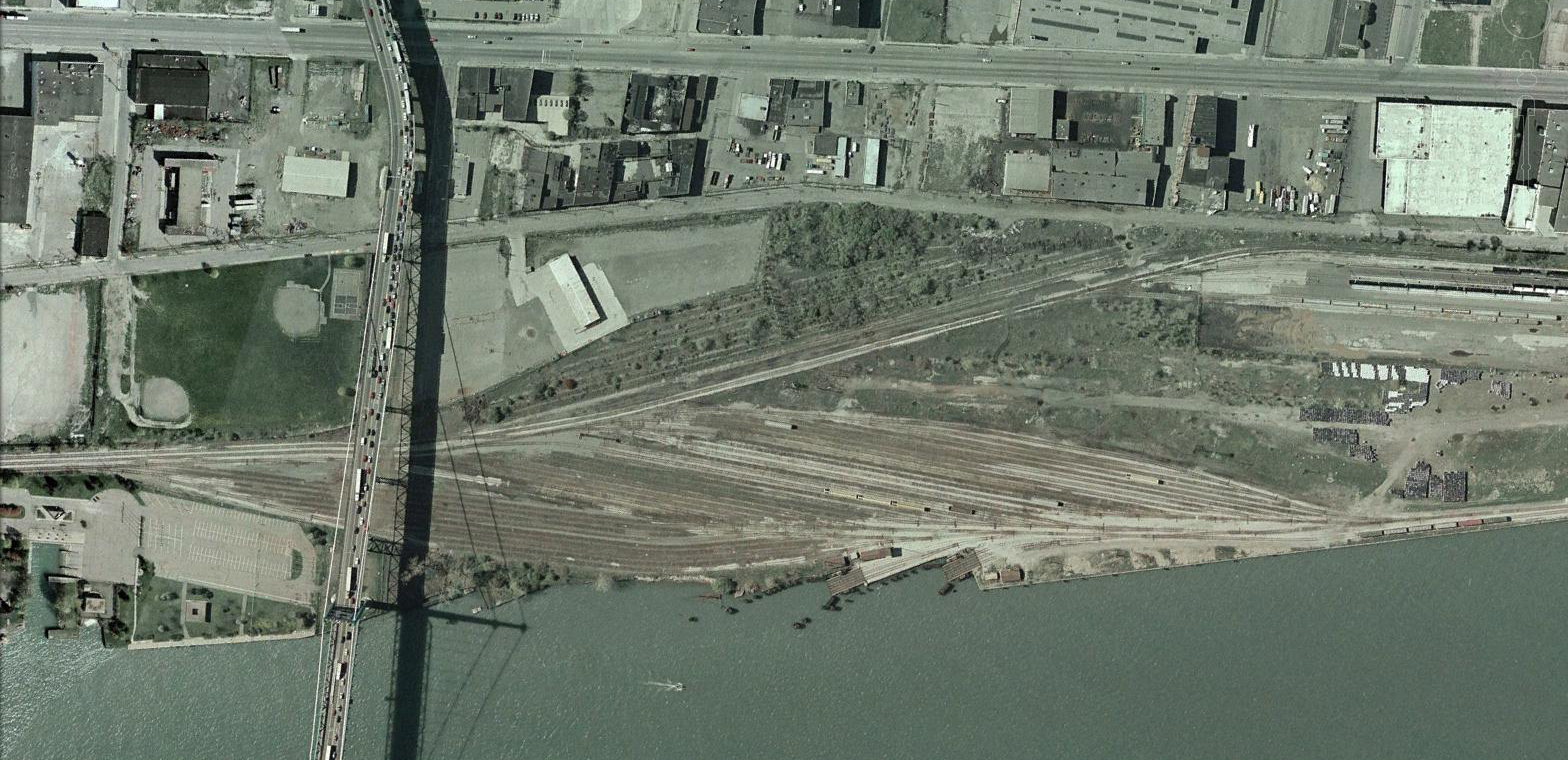
Since I did the first article, Free-mo Module Concepts – Rail-Marine back in August 2013, I have been toying with plans for a Free-mo module set loosely based on the N&W Detroit river operations of the 1970’s. The original N&W yard was located in Detroit adjacent to the Ambassador Bridge to Canada.
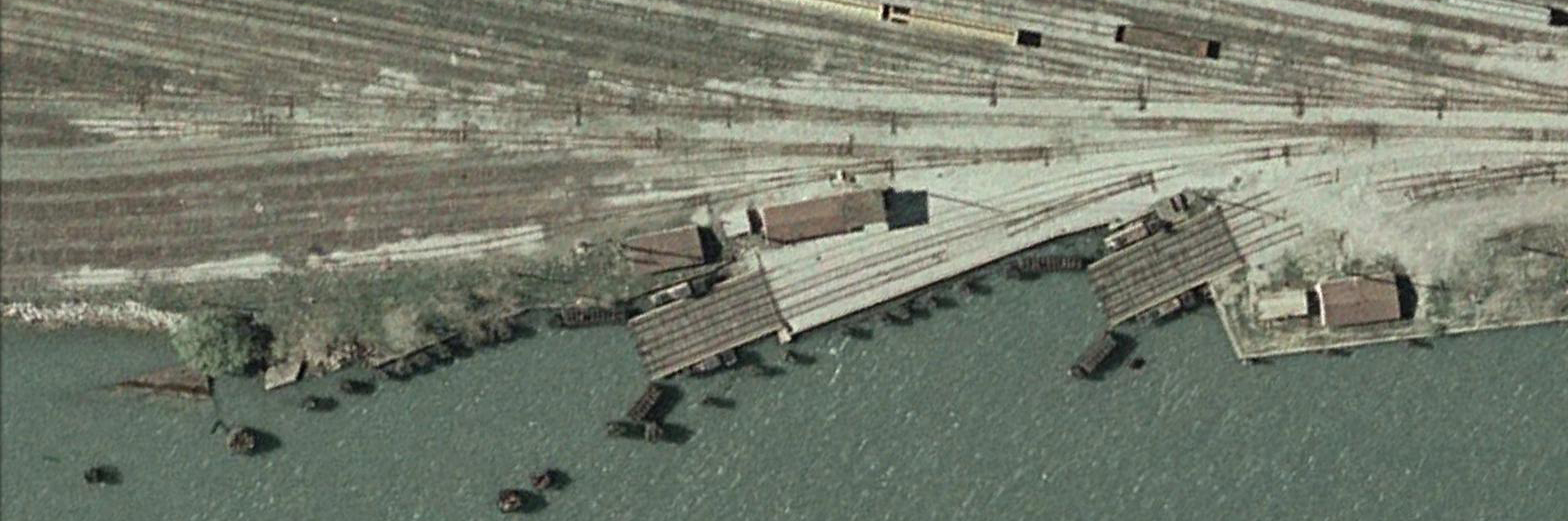
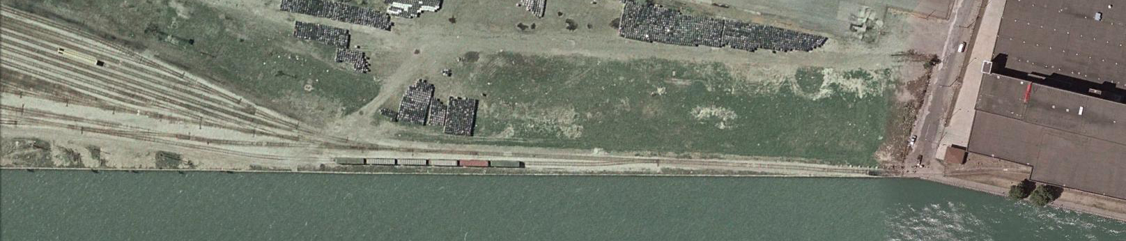
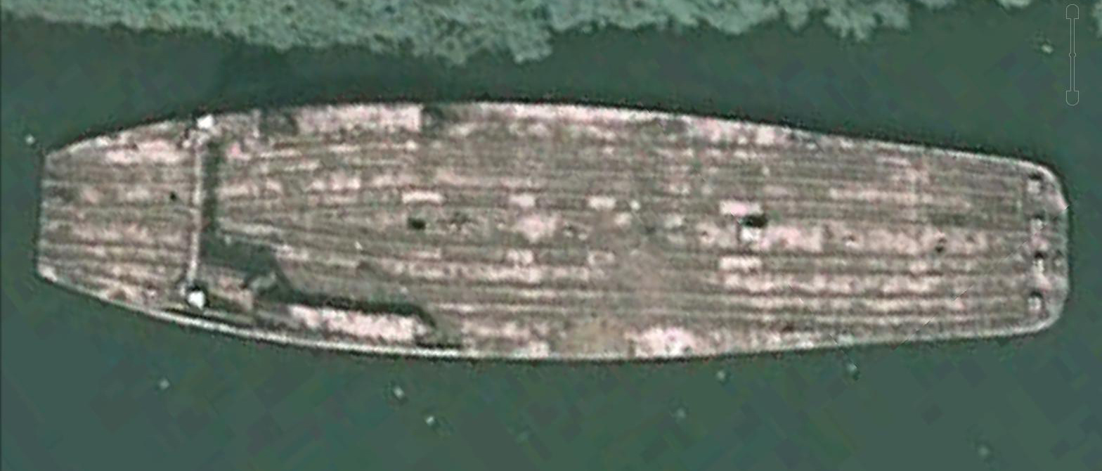
The car float yard was part of a larger yard used for various purposes. Satellite images of the yard are available in Google Earth’s historical data from 2002. A close-up look shows that the tracks available to the car float aprons were a small group of eight tracks. I will refer to these eight tracks as the car float yard. The rest of the adjacent yard appears to have been used for other purposes. Using the Ruler tool in Google Earth, the total length of the car float yard was approximately 1,800 feet. That equates to over 20 feet in HO scale. The tracks varied in length from about 1,000 to 1,200 feet (11.5 to 13.8 feet in HO scale). None of these measurements include the switch lead.
As can be seen in the satellite images, the N&W had two car float aprons. The eight tracks were used to service both aprons. The largest car float, the Detroit, was four tracked and had a length of 308 feet. If we use 300’ as the maximum length for a track, then a float could take a maximum of 1,200’ of cars. This is equal to the length of most of the tracks in the float yard, so one track equals one car float of cars.

Another interesting operational aspect of the N&W car float yard is that it had a short (for prototype) switch lead. An industry was located at the end of the lead that limited the amount of usable lead for the car float operation. There was also a small passing siding and a connection to the rest of the yard.
For the car float operation, a short switch lead works fine. Loading a car float must be done slowly and with only a few cars at a time. Loading cars must be done by alternating cars on each side of the float when loading and unloading. If only a single 300 foot string of cars (remember max length for one track on a float is 309’) was switched at a time, a 500 foot lead (5.75 feet) is adequate for switching the car float with a locomotive and up to two idler cars.
For my design, I have to consider how large the module set will be because I will have to transport it all. I have found that 4’ modules are easy to handle if I am by myself. A stack of 4 modules (6.375” tall) with 1.25” spacers would be 30.5”. I will add 4” casters to the bottom of the stack which will add 5” in height for a total stack height of approximately 35.5”. These dimensions should be able to fit in most minivans. I do own a pickup truck with a full size bed (4’ x 8’) but I cannot always guarantee that I will always have it available. Making the transport size as small as possible allows for flexibility.
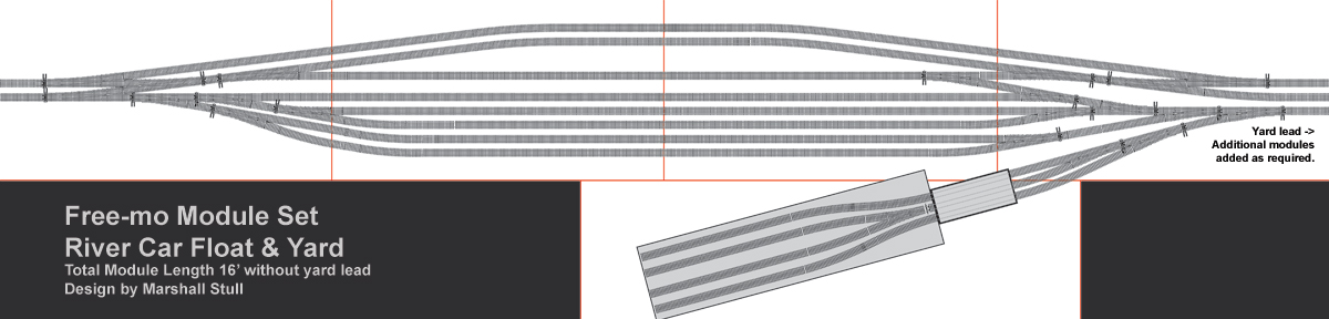
The track plan I developed is a through design with a double track main line. All turnouts that deviate from the main are #8 while yard turnouts are all #6. The main line moves to the outer edge of the modules to make room for the float yard in the center. Crossovers are provided at each end so trains may enter the yard from either end. The top two yard tracks are for arrivals and departures. The four lower tracks are for shuffling cars to and from the car floats. Each track is at least 8’ feet long which can hold just over half of a car float full of cars. This arrangement allows room for unloading a full load while accepting traffic on the A/R tracks and a full car set ready to be loaded.
The extra space between tracks resulted from difference in geometry of the #8 turnouts. I decided to leave the spacing and allow the main to be some distance from the yard tracks to add some visual interest. I am planning on filling those areas with crew shacks, parking, yard/marine debris and other items.
As with all plans, this one has a few disadvantages that are readily apparent to me. The top A/R track is shorter and will only accept an inbound train of 6.5’ in length. Since there are two A/R tracks, the train can be broken if necessary. There are no provisions for locomotive or caboose storage. This should not be an issue as this is not a classification yard. Locomotives and their cabooses are expected to leave soon after arrival. The size of the car float will require an additional module of 5-6 feet in length. This will be an odd size and not fit the stacking I can do with the yard. The yard lead will require an additional five feet of space minimum. I can see no way around this and will most likely make the lead modules match the size of the float module so I can at least stack them together.
This design is not set in stone yet, but I do want to move forward soon. I would like to at least have a working set of modules for the yard by the 2016 National Train Show in Indianapolis. I welcome all comments and suggestions. I will post revisions here as they happen.
How neat! I am building a 3 section Module with a sawmill complex in the middle section.
i would like to see the plan!
I’ll be watching this with interest. I’ve just completed track laying & wiring on a small sectional layout that features car float operations. My intent was just to model the immediate unloading operations, not the entire classification process that a larger yard would require. The 4 track stub yard has just enough capacity to hold 2x the float capacity. If you’re curious you can see the plan here: http://model-railroad-hobbyist.com/track-plan-database?page=10#comment-131895
Regards,
Christian
Very nice design! I am re-designing this one. It is a bit too complex and I think I need to re-think how the yard will be used.