I have been using strip LEDs for my layouts since they became affordable. Although most people think of LEDs as low power consumers, try stringing a few hundred together. My Mound City 1862 layout uses two LED strips of about 6.5 feet each and they are high density (120 LEDs/M). One strip is warm white and the other is cool white. Each alone gave a color I felt was either too blue or too beige. The two mixed together gave what I felt was a nice balanced color that I found pleasing to the eye.
Having insufficient power will lead to only some of the LEDs illuminating, irritating flicker or cause the LEDs to appear dim. To calculate the power supply required for your LED strip, you need to know:
- Length of the LED strip
- Number of LEDs per meter
- Power consumption per LED
To calculate the size of power supply (in Amps) you need to multiply the length of the LED strip by the number of the LEDs per meter and then multiply this by the power of a single LED. Then divide the value by 12 volts to calculate the required Amperage of the power supply.
(Length of LED Strip x LEDs per METER x LED Power) / 12
I recommend you add at least 10% to the calculated value to allow for resistance and losses in the wiring. For my layout I used the following formula:
2 meter (approx 13 feet) of SMD3528 Warm White with 120 LED/M would be; (2m x 120 x 0.08)/12 = 1.6 amps + 10% = 1.8 amps
2 meter (approx 13 feet) of Super Bright SMD3528 cool White with 120 LED/M would be; (2m x 120 x 0.2)/12 = 4 amps + 10% = 4.4 amps
Total Amps = 6.2 Amps
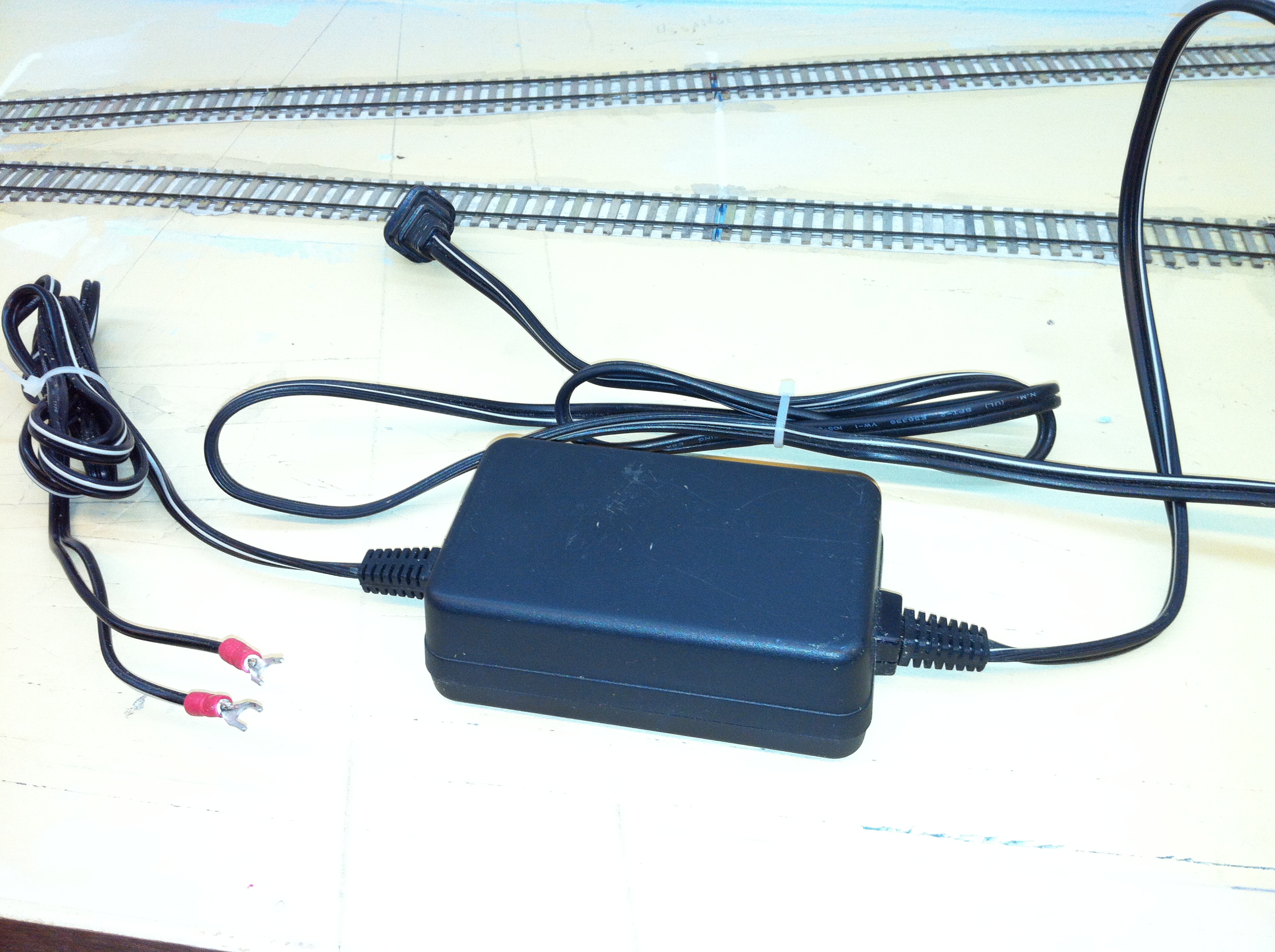
Although the power required 6.2 Amps, I had a 6 Amp power pack from an old printer. Being very close to the correct value I decided to use it. I noticed that the power supply was hot to the touch and knew I would have to replace it eventually. Sure enough the day came sooner than later. As I worked on the layout one day, I soon found myself in the dark. Time to find another power supply!
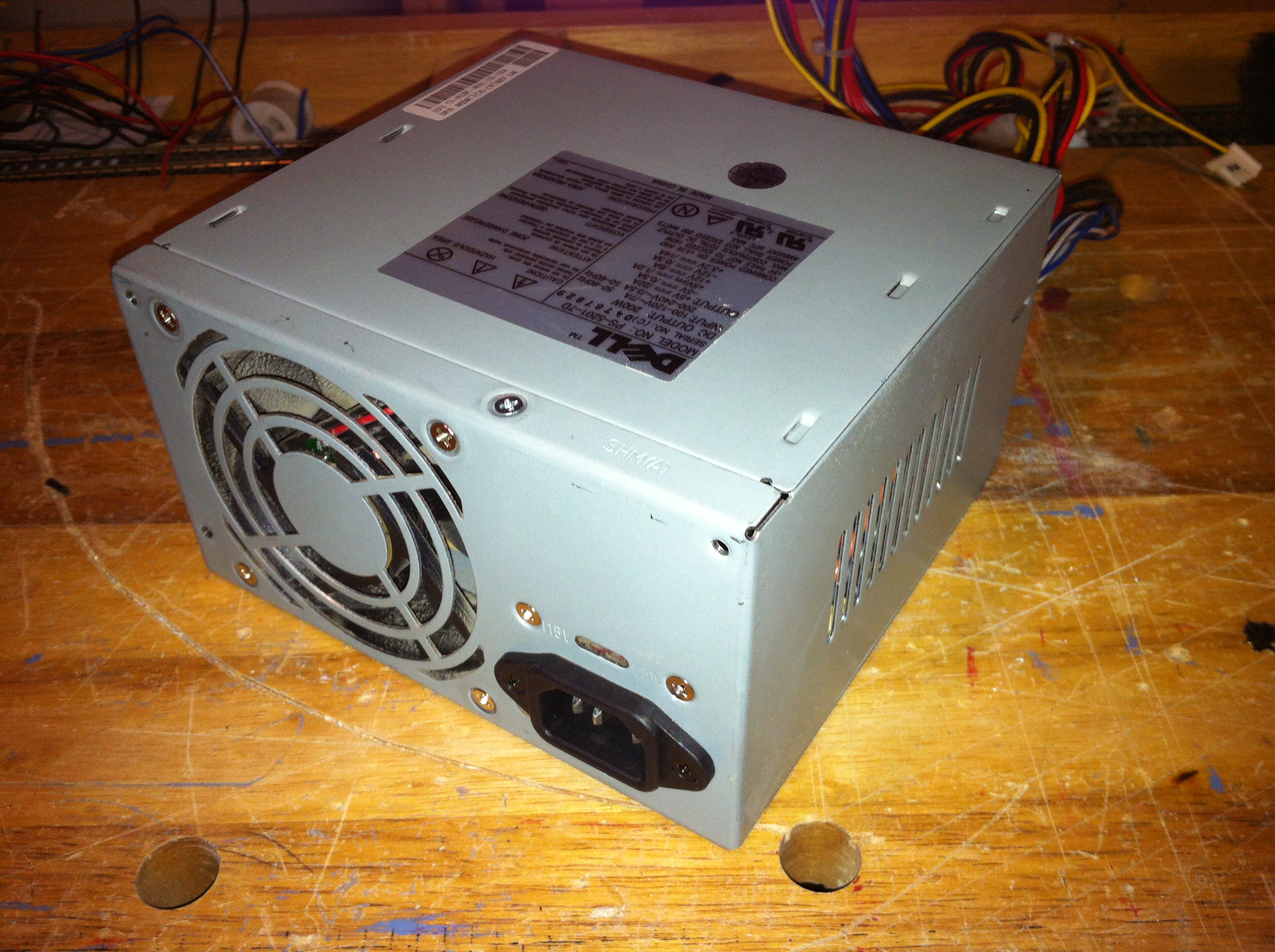
Power supplies of more than 6 amps can be pricey if purchased new. I had several old computers that were destined for the recycle heap and thought I might be able use one of their internal power supplies. After checking several web sites for information, I found that these could be a viable power source for the entire layout. A supply of about 14 Amp could power the LED lighting and all my other needs as well. Computer Power supplies have outputs of +12V, -12V, +5V, -5V, +3.3V and a common ground. You should check the tag on the power supply carefully. The tag will list the Amps for each voltage. In my case I choose a Dell 350 Watt supply from an old server. This had 14 Amps on the +12V line and even more on the +5V line. This would be more than enough power.
Now because we working with electricity, we have to do the legal stuff for those who are not responsible for their own actions:
WARNING!
Computer Power Supplies use high voltages and contain capacitors that may inflict injuries even when not plugged in!
Disclaimer: The information presented should not be considered a “HOW TO” article, but merely a documentation of my conversion process. Modern PC Power Supplies can produce high output current levels that may cause internal overheating in the PS or damage to devices connected to them. Any individual attempting their own conversion is cautioned to carefully research their PS specifications and to be mindful of the associated voltages and power. DO NOT work on your opened power supply with it plugged in!
Wires
The first thing you notice about a power supply is the spaghetti hanging from it. It is not as daunting as it may appear. The same circuit (wire) is used many times over in multiple connectors.
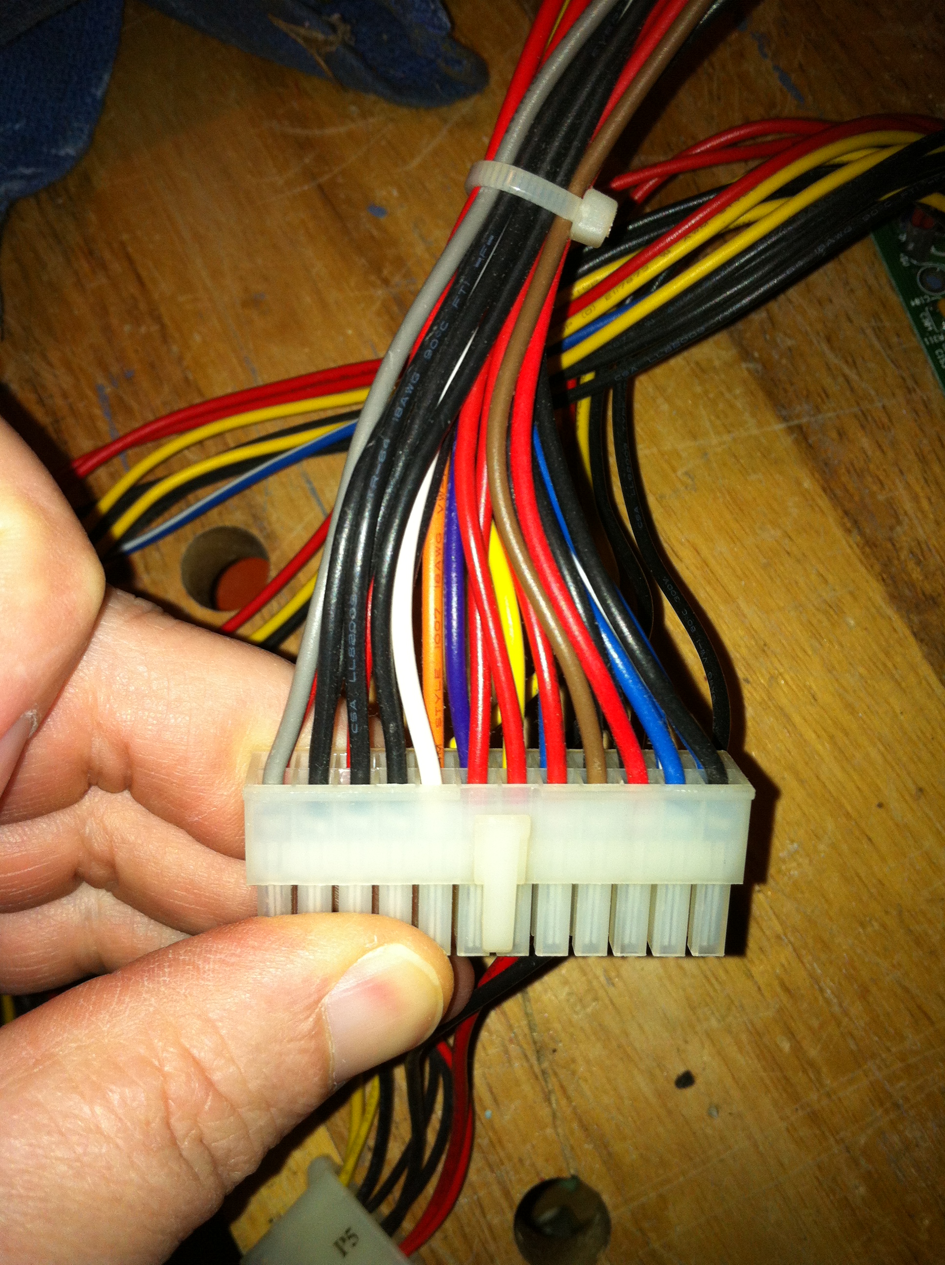
Most PC power supplies use common color coding for their wiring as follows:
- ORANGE = +3.3 V
- YELLOW = +12 V
- BLUE = -12 V
- RED = +5 V
- WHITE = -5 V
- BLACK = Ground
- GREEN = Power-On (short to ground to power up)
There may also be a few other colors with unique uses for the computer such as:
- GRAY = Power-OK
- PURPLE = +5 V Standby
- BROWN = +3.3 V Remote Sensing
NOTE: Always verify your power supply wiring colors before starting. Some manufacturers did not follow this color pattern!
For my use, I am only interested in the +12V and +5V lines. My Dell power supply deviated from the standard as follows:
- +12V = Yellow
- +5V = Red
- +3.3V = Blue/White stripe
- GRND = Black
- -12V = Blue
- -5v = White
- Power-On = Gray
- Load Resistor = Red (see below)
I cut (or covered) all the wires I would not use. That left me with the following:
- 2 Yellow Wires (combined to one connector)
- 6 Black Wires (2 each to 2 connectors, one to load resistor, one to On/Off switch)
- 2 Red Wires (one for load resistor and one to connector)
- 1 Blue/White stripe
- 1 Blue
- 1 White
- 1 Gray (to On/off switch)
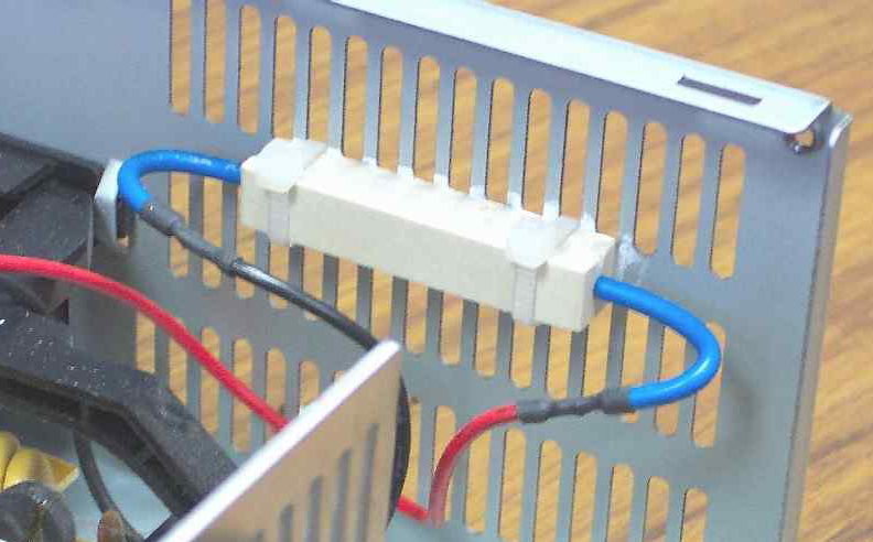
Load Resistor
Power supplies need to see a load on the +5V circuit before they will power up to full strength. Some designs will even fail if there is not a load. For our use we need to add a Load Resistor to imitate this. I took one of the red +5V leads and one of the ground leads. Between them I placed a 10 ohm/10 Watt resistor. I used some Heat Sink Compound and tied the resistor to the case so it acted as a heat shield.
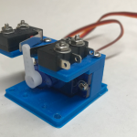
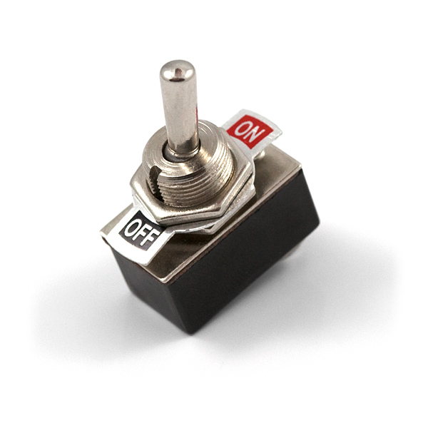
On/Off Switch
Next I drilled a hole in the case to add an on/off toggle switch. This takes the place of the button on the front of the computer. You could just hard wire the Gray and Black wires together without the switch, but I think it is better to have a switch than to have to unplug the supply every time. I used a simple SPST toggle switch and soldered the gray and black leads to either side of the switch.
Spade Connectors
Since my layout uses terminal strips, I used simple spade connectors on the wires. I did use two wires for each of the grounds and +12V circuits. This is because I expect to use some high amps on the +12v circuit. When I was done I had the red (+5V), a black (companion for the +5V), a yellow (+12V) and another black (companion for the +12V). I am not currently going to use the other wires but may in the future, so I sealed the ends, tied them up and set them aside.

Results
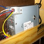
With everything completed, I placed the new power supply in position on the back of the layout. My design created a shelf at the back of the layout that conveniently acts as a channel for the wiring and power supply. Make sure that you leave enough room around the vents and the fan for the power supply.
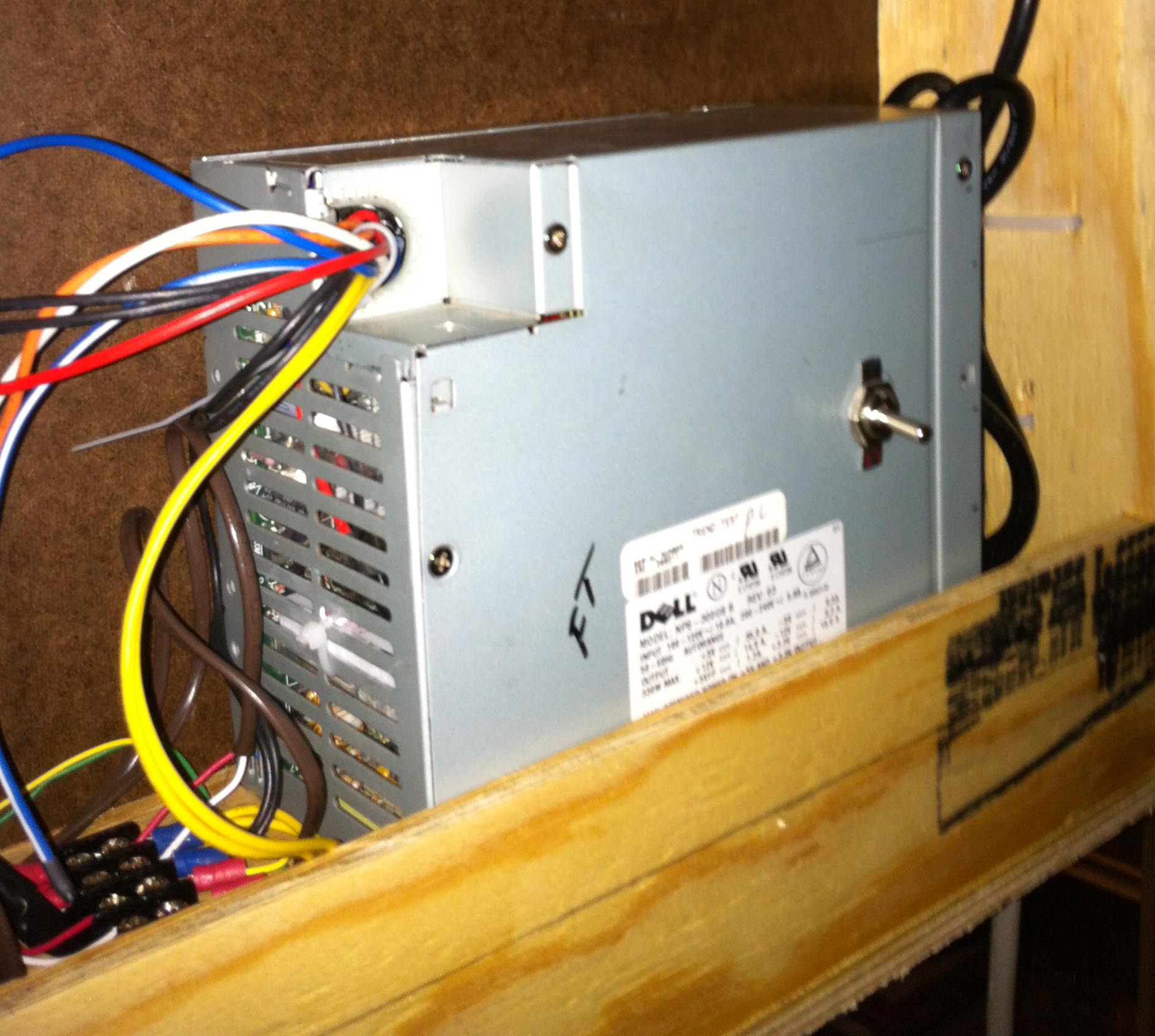
The lights and switch motors all worked great. Now I can continue with the scenery!
I found the following sites very useful for information on using computer power supplies:
http://web2.murraystate.edu/andy.batts/ps/powersupply.htm