 While researching how to light my Mound City 1862 display layout, I received some very innovative lighting recommendations from Joseph Norris. I met Joseph through the Yahoo Small Layout Design Group.
Joseph has been experimenting with a lighting design using bright LEDs that can easily be dimmed manually or electronically. He made his own circuit cards to control the lights, which includes programmed lighting on a number of buildings as daylight turns to night and the reverse. His small module uses this system and is lightweight, unintrusive, as bright as daylight and easily controlled.
I found this to be exactly what I needed for my display module. With permission from Joseph, the following is a presentation he gave at an SER Division 15 meet.
Small Layout Enclosure
Construction and Electronics
October, 2011
Joseph Norris
SER Division 15
Development of these small layout enclosures was undertaken to examine the following:
- A ‘standard’ module for a portable home layout
- A module to be used for display at train shows
- A module for purposes of experimenting with scenery designs
The controlling parameters were:
- Ability to fit into a fourdoor sedan for transportation
- Light weight and easily transportable
- Integral illumination
- Provision for both continuous running and operations
- Operation from the front
The overall size of the modules is to be determined by the following:
- Size of backdrop material, in this case matte or poster board
- Size of back seat and trunk opening in the automobile
These criteria led to acceptance of a maximum width of 401/2”, height of 18” and depth of 24.” The base size of 401/2 by 22” allow for continuous running in HO narrow gauge scales and smaller.
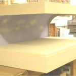
To meet the ‘light weight’ parameter, 1” extruded insulating foam and ¼” Sande Ply® plywood were used, providing a sturdy and reliable structure weighing about 6 pounds. The extruded foam provided the basic internal structure. It was surrounded on three sides with plywood coverings to provide reinforcement and a smooth, paintable surface for finishing.
CONSTRUCTION
These construction details apply to a module of the larger dimensions mentioned above. Foam pieces were cut first, using a carefully aligned table saw. Pieces that shared a dimension were cut with the same saw setting.
Six pieces make up the primary construction, as shown on the next page. The more challenging pieces are the two sides, which must be cut out to permit viewing from the sides. The backdrop fits within this cutout and is arched toward the back to represent a ‘curve’ in the skyline. This curve is entirely arbitrary to suit the preference of the builder. The sides should be laid over one another and secured in alignment. The cutout is drawn on the top piece from a prepared template and cut out with a Saber saw, band saw or jigsaw, then separated again for installation.
_img_0")
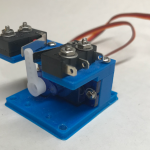
Additional bracing can be added by making more 4” X 38” X 1” panels; perhaps one along the top of the back and another between the two sides, Front to back bracing can be added once it is determined where the base must be clear on its underside, for example – where turnout motors are to be installed. These braces will have a cutout in several places to allow electrical wires to pass through.
_img_1")
The foam is cemented with Liquid Nails “Projects and Foamboard Adhesive.”® This material is not recommended for foamboard to foamboard adhesion by the manufacturer, but seems to work well nevertheless.
Pieces are glued and clamped and left to dry overnight (8 hours or more). Only a thin layer of adhesive is required. If the coat is too thick, it may be difficult to maintain part alignment during the first hour of setting time. If carefully fit, there should be no further operations on this basic structure
_img_2")
In this photo, the sides are being glued to the back. The 4” sections are not being glued at this time but are in place to help hold the sides perpendicular to the back while the glue is drying.
Only a light clamping pressure is required. After clamping, check the clamped pieces every ten minutes during the first hour to be sure they haven’t shifted.
Preparing the Backdrop
The backdrop (matte board or poster board) should be fitted before continuing. Eventually it will be glued to the upper inside curve of the sides. Its width must be trimmed to exactly align with the outer edge of the sides, and its length must extend from the lower point in the curve around to the end of the top.
Once it is fitted, the backdrop can be painted, perhaps just with blue, keeping in mind that the sky appears lighter as it is viewed closer to the horizon. Spray painting with lacquerbased paints works very well. Waterbased paints must be used with caution, although many have had good results with thinned acrylics.
Preparing the Plywood
Plywood pieces are cut to overlap the two sides, the proscenium and the fascia. They are made of special light weight plywood, ¼” thick, and glued to the foam with Liquid Nails.
The side pieces are exactly as wide as the sides but higher by about 3/8”. The cutout has the same general shape as the foam, but is a little smaller so that the plywood is proud of the foam curve to hide the joining of the backdrop to the sides.
_img_3")
The base rests on the top of the supports, adding 1” to the height. The plywood cutout can be adjusted to cover all or just a portion of the base height. Many prefer that at least a little of the base is exposed. If so, it facilitates running track between modules, since the plywood is not interfering with the track.
The fascia will be cut to the height as the bottom lip of the side cutout plus a little more, allowing it to cover all or part of the base. The proscenium will overlap the backdrop to hide it from full frontal view where it meets the front of the module. Note that the proscenium and fascia overlap the exposed ends of the sides.
All plywood pieces are carefully sanded, sealed with a coat of shellac and sanded again with fine grit paper. Before gluing to the foam frame, the areas of the sides that will be visible on the inside of the module are painted in the finish color. This can be seen in the photo on the right.
_img_4")
The sides are glued to the foam frame first, their back edges flush with the back. After drying, the proscenium and fascia are glued to the front. Liquid Nails is used to secure the wood pieces to the foam. Clamping is recommended for a strong bond.
_img_5")
Installing the Backdrop
The matte board backdrop, now painted, is 40” X 32” and about 1/32” thick. Therefore it is rigid enough to help stabilize the foam frame and also rigid enough to resist conforming to the curved part of the frame.
To facilitate installation, contact cement is used, allowing a quick bond as the backdrop is bent to conform to the foam cutout. Contact cement will react chemically with the foam and seriously disfigure it, therefore all foam surfaces that will secure the backdrop must be protected. Thin poster board was used in the module, cut to size and secured with yellow woodworker’s glue. The photo on the right shows the strips installed. Contact cement will be applied to the strips and the backdrop before installing it to the frame.
_img_6")
Backdrop installation is best done by two people, one at each side of the module. The frame is placed on its back and areas of the frame with contact cement are temporarily covered with waxed paper to prevent premature contact with the backdrop. The backdrop is first seated in the grooves cut in each side, then pressed into place around the curve, moving the waxed paper out of the way as installation progresses. The front edge of the backdrop is pressed against the underside of the front foam brace
LIGHTING
Overhead lighting is provided by LED segment strips, 3 LEDs to a segment, each segment 2” long by 5/16” wide. The segments have a selfstick and are available in continuous rolls, electrically connected, and can be cut to any length divisible by 2”.
With an interior height of 14” to 18”, LEDS can be placed across the ‘ceiling’ of the module in rows, each row spaced about 4” apart and lying flat against the ‘ceiling,’ attached with their selfstick adhesive.
![]()
These LEDs provide a bright and even illumination of the entire base, in a hue that closely resembles daylight. They achieve full brightness at 12 volts and extinguish at about 7 volts. Each segment draws about 25mA. Differing segment lengths can be connected in parallel and fed from a common power supply.
Horizon lighting can be provided by a single row of segments that project upward from behind the base as shown here.
_img_8")
_img_9")
_img_10")
Overhead LED segments are wired on the top side of the backdrop and fed down below the base through small channels cut into the foam. The power supply is located inside the base area.
_img_11")
_img_12")
_img_13")
_img_14")
CIRCUITS
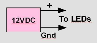
Power for the LEDs can come from a 12 volt DC power supply, particularly the kind that plug into a wall outlet. These are available from surplus houses. This simple supply can be illustrated as shown here.
Each LED segment begins to emit light at about 7 volts and achieves maximum brightness at just under 12 volts.

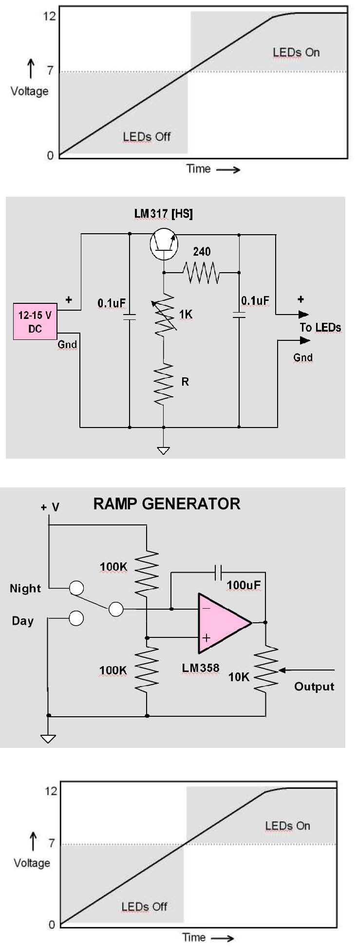
Manual dimming can be provided by using a LM317 voltage regulator and a potentiometer as shown on the right. The value of the resistor R is set to provide an output between 7 volts (dim voltage) and up to 12 volts DC. A typical value for R is 1200 ohms. The regulator itself has a voltage drop of about 2 volts so, for full illumination, a power supply of at least 14 volts is required. The LM317 will need a heat sink.

Automatic dimming can be achieved by linearly charging and discharging a capacitor in a simple opamp integrator. The direction of the ramp output (up and down) is controlled by a SPDT toggle switch.

Remembering that the LEDs do not light until they are excited by at least 7 volts, it is useful to add 7 volts to this ramp voltage so that its entire excursion results in a varying light output.

The chart above illustrates the issue. Half of the ramp voltage will be wasted unless some additional circuitry is provided.
The solution is to ‘add’ the ramp voltage to an offset voltage. The opamp ‘adder’ shown below does just that. The 1K potentiometer is set to a voltage just below the turnon voltage of the LEDs. As the ramp voltage changes, it is added to the offset and the sum is presented at the output.
_img_17")
_img_18")
The final step is to provide current amplification adequate to power the LEDs. The TIP102 will provide more than enough power (up to 50,000 LEDs!). The output of the ‘adder’ is connected as the input to the 10K resistor.
_img_19")
Structure and Scenery Lighting
The same varying voltage output that powers the overhead lighting can be used to control lighting to structure and other scenery lighting on the diorama. Suppose, for example, that street lighting appears at a specific level of overhead illumination and that various structure lights appear at other levels of illumination. This can be achieved by feeding the ramp voltage to a ‘comparator.’
_img_20")
A comparator is a special opamp with two inputs. One input is a reference, illustrated by the + input in the schematic on the right. The potentiometer provides a ‘reference’ voltage to the comparator. We can connect the ramp voltage to the – input of the comparator.
As long as the reference voltage is lower than the ramp voltage, the output of the comparator is ‘off.’ When the ramp voltage exceeds the reference, the output is ‘on’ energizing the relay. The relay controls the structure lighting.
By using a number of comparators, each powered by the same ramp voltage and each with a different reference voltage setting, structure lights can be turned on at different times as the overhead lights dim, and turned off at different points as the overhead lights become more bright – all this taking place within the time of the ramp interval.
Since the LM339 has four comparators in a single chip, four different voltage settings are available with a single chip.
The following is the completed circuit (click to enlarge).
_img_21")
SOURCES
Sources for general materials used in the construction of this diorama are listed here. Prices are as of October, 2011.
Extruded Foam
Known as ‘blue board” or “red board”, these insulating materials are available in thicknesses from ¼” through 2”. 1” thickness is usually available from building supply houses and occasionally from Home Depot and Lowes. Prices vary considerably but $30/sheet is a close estimate. A single sheet will build several large modules.
Adhesive
Liquid Nails (Projects & Foamboard). Item # LN604. Hardware and Home stores (Lowes, Home Depot, etc.) Price: $1.74 per tube. (Only part of one tube was used in this diorama.)
LEDs
All Electronics Corporation. www.allelectronics.com. 8008265432. Van Nuys, CA. White LED strips, 50mm long (2”) each with 3 LEDs and current limiting resistor. Operating voltage is 12 volts DC. Strips can be ordered with any number of 2” segments joined in a continuous strand with intersegment wiring in place. Individual segments can be cut away from the strand. Current requirement is 25mA per segment at full voltage.
Three shades of light are available:
Item # LS12CW, Cool white (fluorescent)
Item # LS12NW, Neutral white (a ‘natural’ light, used in this diorama)
Item # LS12WW, Warm white, closer to incandescent bulbs
Price: $2.35 per segment. 10 for $1.75/segment. 100 for $1.55/segment.
Plywood
¼” plywood distributed as ‘Sande Ply’, made in Ecuador by Endesa, and available from Home Depot stores. This is a light weight material, available in full 4’ X 8’ sheets, 4’ X 4’ and 4’ X 2’ sections. Plywood cost for this diorama was approximately $11.00 with material left over.
REFERENCES
“Foam Core Layout Base” http://home.earthlink.net/~elfrohirrim/id20.html
“Foam core module” Prof Klyzlr. http://carendt.us/scrapbook/page87/pdf/FoamcoreModule.pdf
I just happened to see this post while I’ve being thinking about a similar idea.
I thought about sequencing segments in a way that the light could represent the sun’s travel across the sky, so the shadows would be realistic.
I have been hoping to do some advanced lighting as well. Thinking about PICAX chips with logic to control them. Maybe even RGB strips to vary colors and do sunset/sunrise sequences. Let me know how you progress.
I’ve actually done this same thing albeit much later than yourself. What I’ve discovered is that for $6.95 you can have the rainbow if you buy the 5050 smd rgb light strips. http://www.ebay.com/itm/IR-Remote-Controller-44-Keys-for-RGB-LED-Light-Strip-/170937524245
I used it on my “C” based ttrak module. I have 3 basic settings. Full sun daylight (pictured). http://www.flickr.com/photos/nscalerail/9609110929/ daybreak/sunrise and nighttime. I’ll try to snap some pics of the other 2 lighting conditions and post them to my flickr.
I am working on another layout with variable lighting and automated sunrise and sunsets using RGB LED strips. Instead of using the manual control, I want to automate it through a timed sequence with sounds and other animations. Thanks for the information!