This month we will take a look at building the legs for our Free-mo module. As I stated in prior articles (FREE-MO MODULE DESIGN and BUILDING A FREE-MO MODULE – PART I) I like everything All Inclusive and make the setup go as smooth as possible. I do not mind taking a little extra time to figure out the details of construction to save me frustration later. The goal is to run trains and spend all day setting up and sorting out modules. This does conflict with our other rule “Light Weight” so we must make the legs from stiff yet light construction methods.
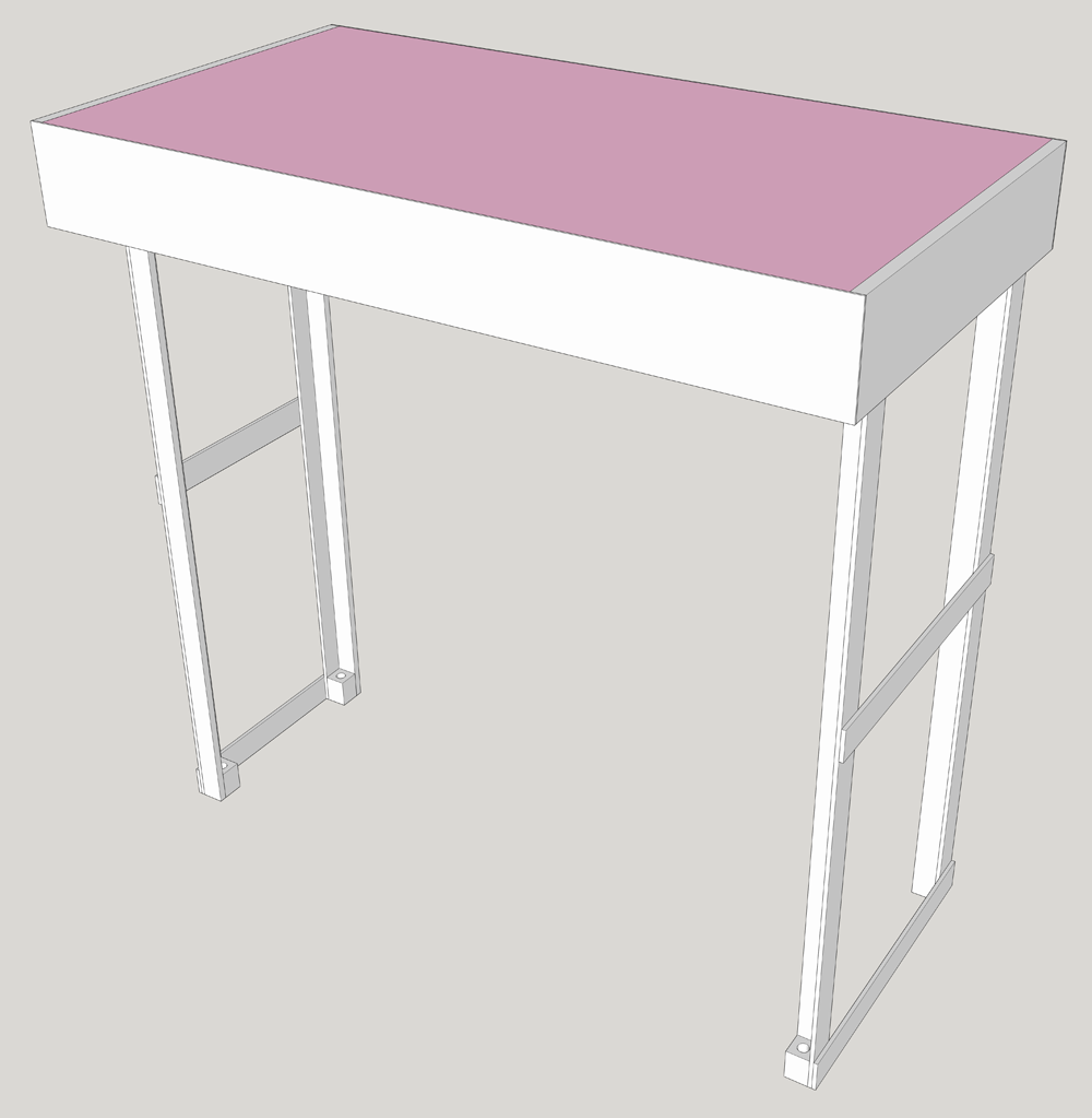
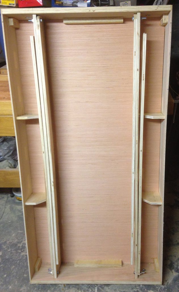
As shown in the FREE-MO MODULE DESIGN article the legs are attached and fold up into the module when not in use. The main frame supports run the length of the module which allows us to bolt the legs directly to the frame without the need for brackets, braces, hinges or other extra hardware.
The four legs must be positioned within the frame so that they will fold in and not hit each other. To do this, the legs must be mounted inside the frame on one end and mounted to the outside of the frame on the other. The assembly of the two sets of legs will be slightly different as a result. To make sure things go together as they should, we will mount the main leg support first before we add the side braces and the foot blocks. This ensures proper assembly.
So that we do not have to add diagonal stabilizers to keep the legs from folding back up or going out too far, the legs are mounted so they press against the end frame when extended. If both sets of legs are extended fully, this will also keep each set from folding in (except if you want to run into it pretty hard before the modules are clamped together). One a free-mo module is clamped to an adjoining module leg wobble does not matter anymore, it becomes a cohesive, stable structure.
The main legs are made from 1/2 inch birch plywood ripped into 1.5 inch strips. The exact length will depend on your mounting location on the leg and the thickness of the top. To calculate the length, measure the distance to the top of the module to the location of the bolt hole (we made this hole when we made the frame) that will hold the leg. The easy way is to mount one leg (long), measure 48.5 inches from the top of the module and mark the leg. Dismount the leg and and cut all the legs to that mark.
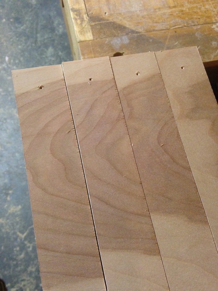
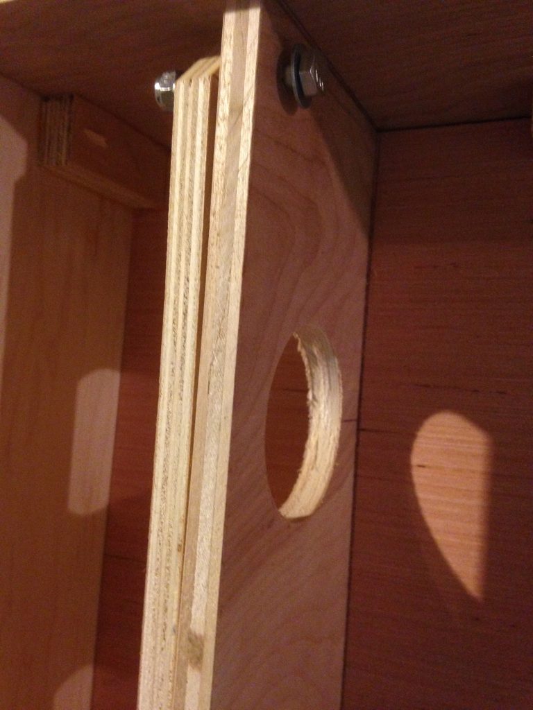
All of the legs will need to be drilled for the bolts. The drill size will depend on the bolts used. Some may want to use brass inserts as bearings so the wood does not wear and cause increased wobble over time.
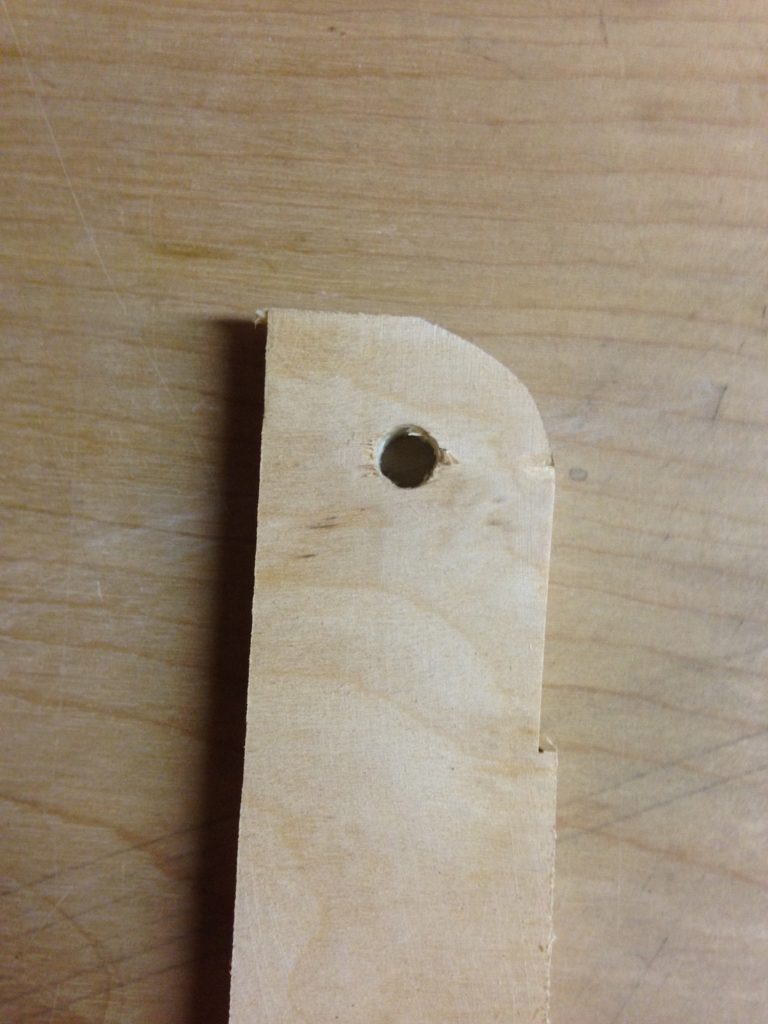
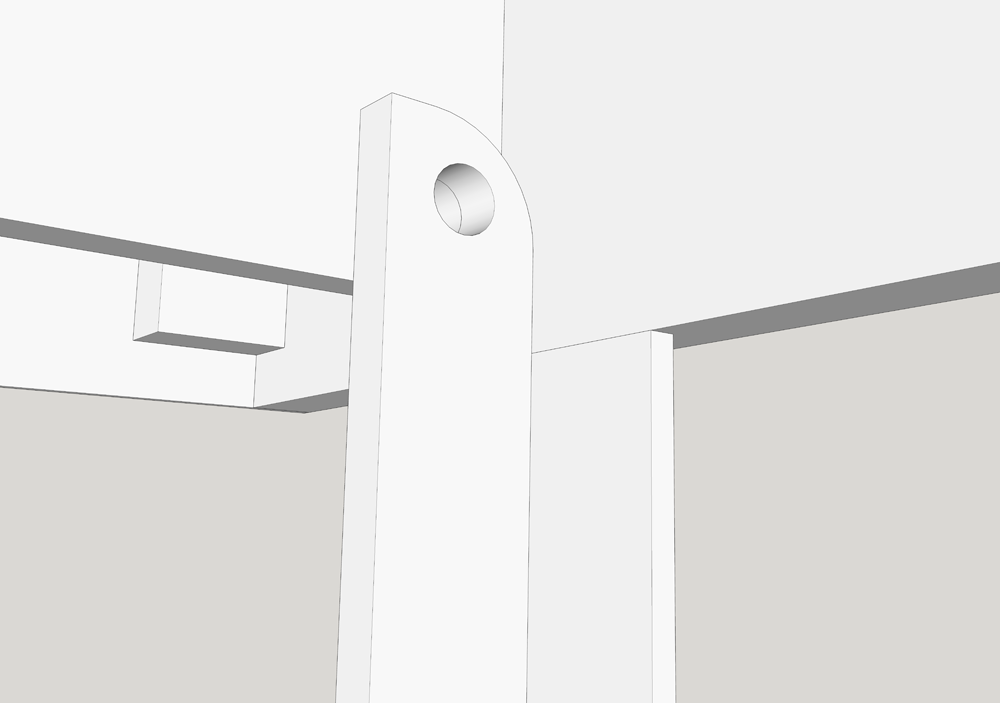
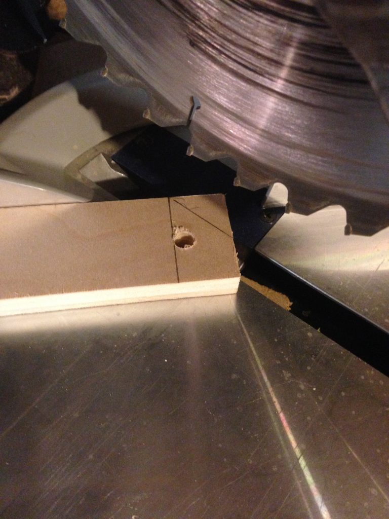
The tops of the legs must be cut so that the leg will clear the frame when they fold up. my original design shows a curved cut to make this clearance. Well having to cut 24 legs to exact curves proved to be more than my patience could take. I change to a simple 45 degree cut that worked out just fine.
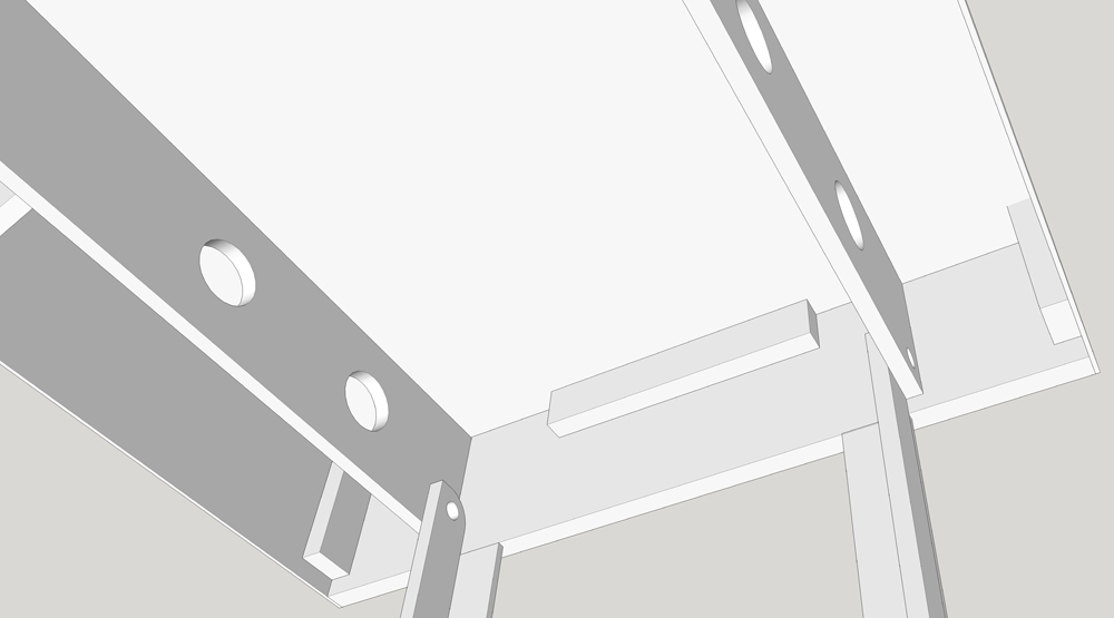
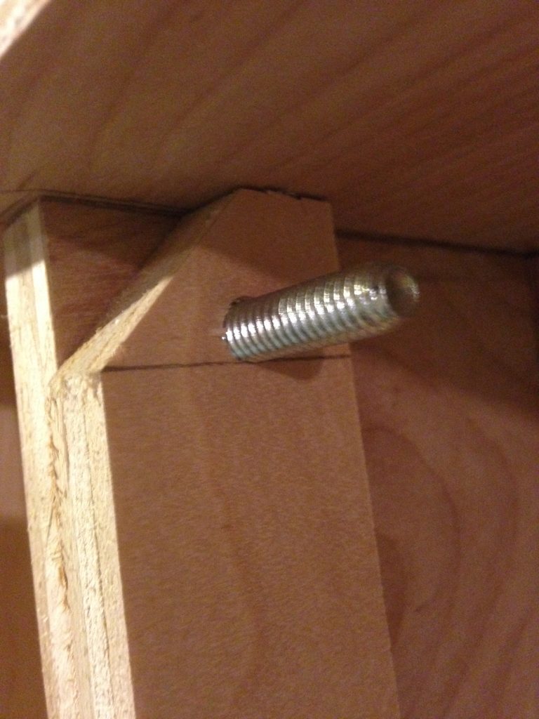
Next we test fit our first leg. DO NOT TIGHTEN BOLTS UNTIL ALL CLEARANCES ARE CHECKED! I used 5/16-8 shoulder bolts with washers and nylon nuts so they hold in place. Here I should mention to find a location that sells nuts and bolts by the pound (like Tractor Supply), it will save you a few dollars.
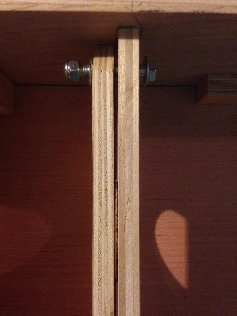
During the test fit we need to check a few critical things. If the leg is too long past the bolt the leg will act like a pry bar over time and separate or deform your end plate. Make sure there is at least a small space between the leg and the end plate when folded up.
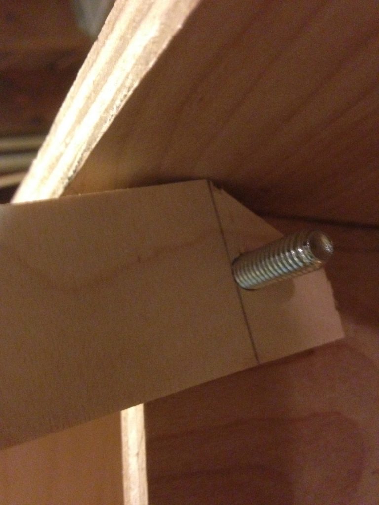
Once the folded position is good, We can extend the leg and check for clearance against the end plate from leg again. This will also deform the end plate if not in the correct position.
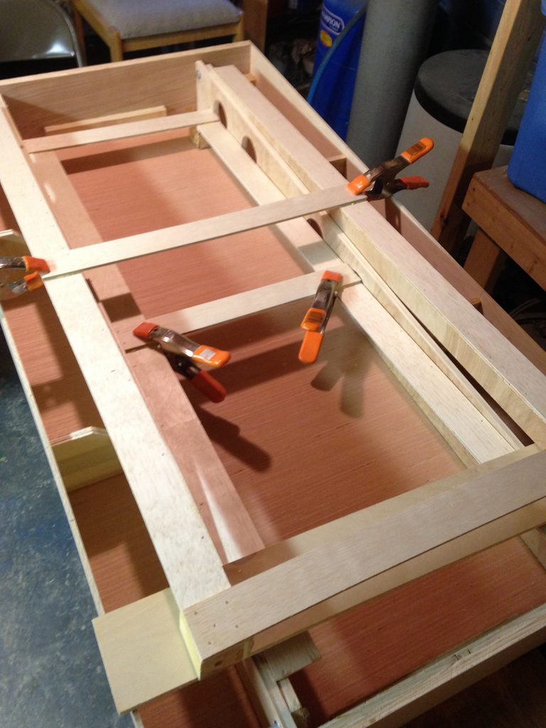
I used a framing T-square clamped to the frame to check the leg when extended. Again, this SHOULD NOT exert pressure on the end plate. If it does, remove the leg and trim some material off. The following image shows a leg extended and you can see in the photo where I had to remove material from the top of the leg with a hand saw or jig saw. You could also use a sander if just a little needed to be removed..
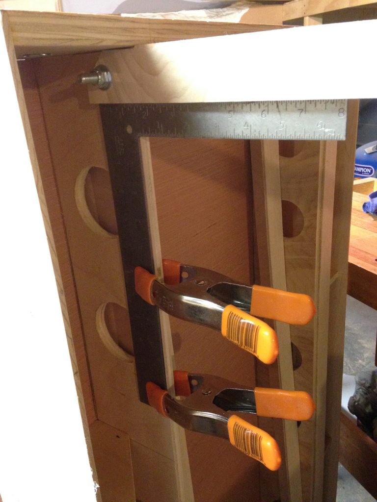
With all four main legs on the module, we can tighten the bolts up snug. DO NOT OVER TIGHTEN! The bolts should be just tight enough the when you extend a leg it will stay in position.
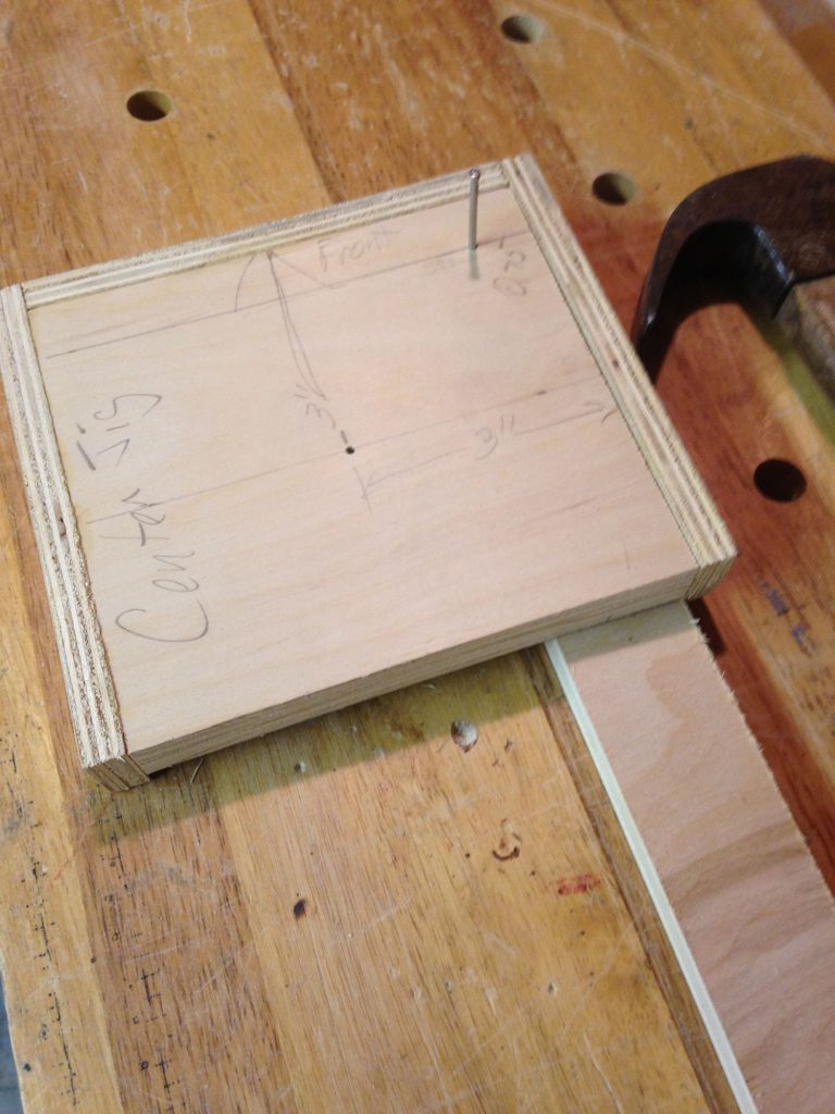
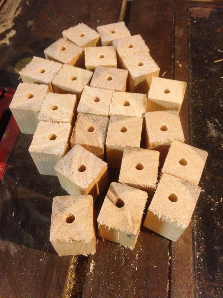
The bottom of the legs will use T-nuts and carriage bolts for the +-1 inch required by the Free-mo specifications. To hold the T-nut we need to make feet from 2×2. One 2×2 goes a long way for this. Cut the 2×2 into 2 inch high blocks, one for each leg. In the center of the block, drill a hole all the way through to fit the T-nut.
The leg sides are cut from 1/4 inch underlayment (or other thing light plywood) and are 2 inches wide. I test fit the first one with the leg extend to get the correct length. I also recommend marking the main leg where it meets the frame so you know where the side of the leg should be when you assemble it.
With all the sides and feet cut, we can begin assembling the rest of the leg. I used carpenter glue and nails (cheap Harbor Freight nail/brad gun makes it go fast) to assemble the leg.
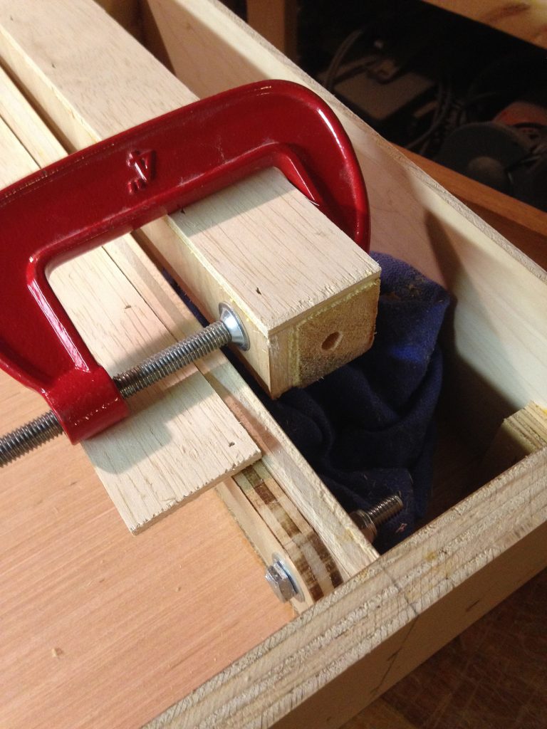
The final step is to add the cross braces. These are also cut from 1/4 inch underlayment. I clamped them in place and tested the fit before making the final cut. Securing the cross brace with wood glue and nails.
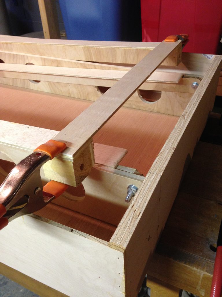
A second set of cross braces is set just above the half way point of the leg. This will make sure that the inner and outer cross braces do not hit each other.
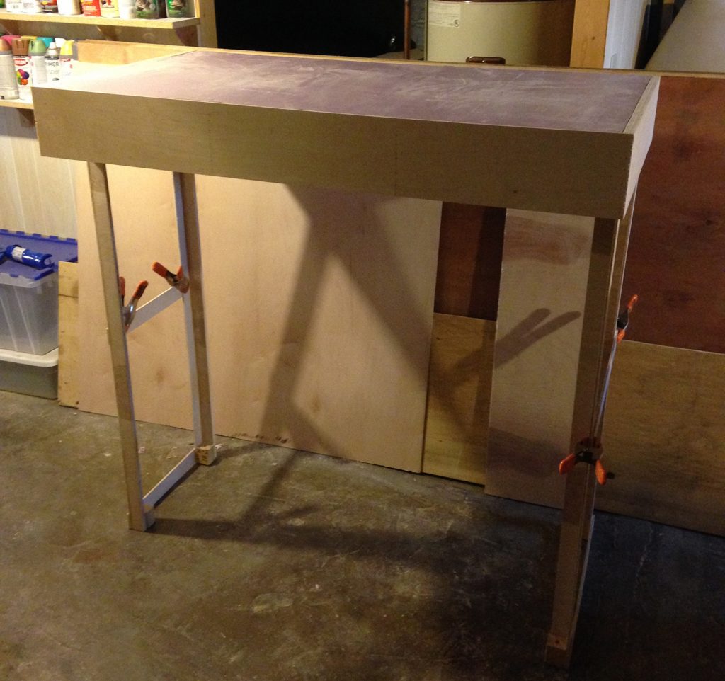
Just add the T-Nuts and the carriage bolts and you are ready to finish your module. I hope you found this article helpful.
Excellent designs and thank you for sharing. Have you considered any provisions for keeping the legs extended during operations? A friend and I are about to build our own Free-Mo modules following your methods and this was a question that came up.
Thank You! There is no provision for locking the legs. What we have found is when several modules have been connected, the legs do not need any further stabilizing. If I do a setup with just these modules, I will use a single clamp at the middle of the legs to keep legs from adjoining modules together. This has proven more than enough to keep the layout from swaying.
Alex, what part of the country are you and your friend from?
Northern California.
Thanks very much for the design ideas, I’m in process of building a 5′ module myself and this has been great info.
I am very interested on how the build goes. Please share your experiences!
How much does this module weight?
It weighs just a few pounds. Mine with scenery is 6LBS. Your final weight will depend on what scenery you apply to it.