In my last article, we looked at a Free-mo Module Design that was light weight, strong and easy to setup among other things. This month we take a look at actually assembling the module and some of the finer points involved.
The overall module length is 49.5 inches. That may seem like an unusual dimension but this is done to save materials and add room for the folding legs. A standard sheet of plywood comes in a width of 48 inches and in Free-mo the end plates must be 3/4 inch birch plywood. Two end plates equals a total of 1.5 inches plus the width of the plywood sheet gives you 49.5 inches. So you have less cutting to do and you take advantage of the standard width of the plywood sheet.
This module design is for a 26 inch wide Free-mo double track module. If you wish to build a single track module simply reduce all widths by 2 inches to create a 24 inch wide module.

The module design uses the following materials:
End Plates
3/4 inch birch plywood – 2 @ 6″ x 25.5″
Side Fascias
1/4 inch birch plywood – 2 @ 6″ x 49.5″
NOTE: Most 1/4 inch plywood is NOT 1/4 inch in depth. Check this before purchasing. I purchased high quality birch plywood that was 1/4 inch. The dimensions used from here on depend on this being 1/4 inch. You may use another material but you will need to adjust dimensions of other items such as the End Plates.
Stringers
1/2 inch birch plywood – 2 @ 4 5/8″ x 48″
NOTE: The height of this piece will change depending on the thickness of the top. It should be approximately 1/2″ shorter than the end plates.
Gussets
1/2 inch birch plywood – 4 @ 4.5″ x 4.5″ with one corner cut off at 2″
Foam Top (sandwich top)
1/2 or 3/4 inch rigid foam insulation (pink or blue, do not use white)
1 @ 25.5″ x 48″
NOTE: MUST BE FLAT. Do not use if ends are curled.
Plywood Top (sandwich bottom)
1/4 inch plywood underlayment – 1 @ 25.5″ x 48″
Legs
1/2 inch birch plywood – 4 @ 45″ x 1.5″
1/4 inch plywood – 4 @ 43″ x 2″
1/4 inch plywood – 4 @ 15 3/4″ x 2″
2×2 pine – 4 @ 2″
Construction
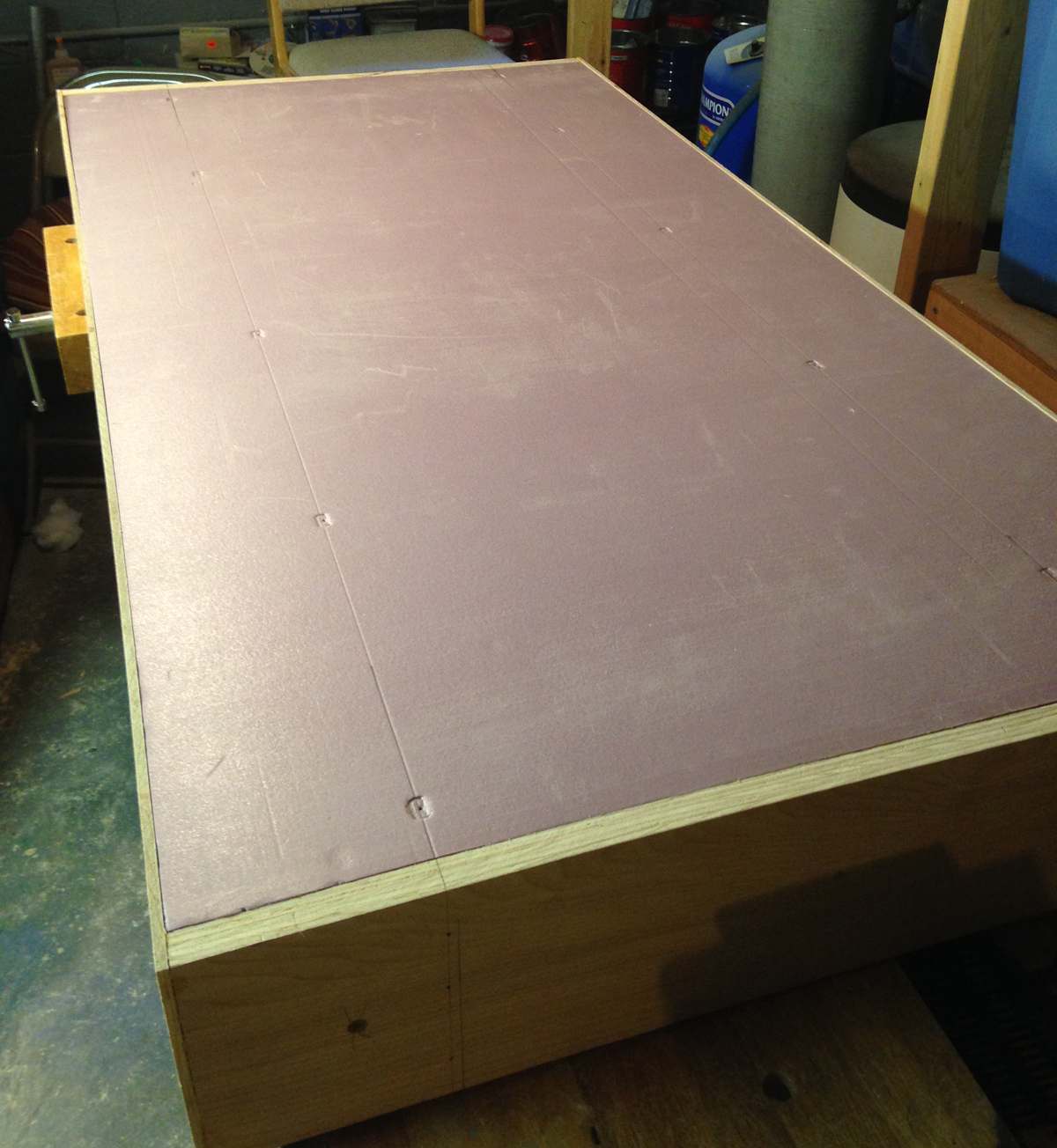
Begin by cutting the foam top and the plywood top. Since the end dimension is 48 inches we only have to cut the side dimension (if you purchased a standard 4’x8′ sheet). This will ensure that our ends are straight and will be flush with the end plates when assembled. The sides are not as critical and small voids will be filled in later.
Using LOCTITE PowerGrab construction adhesive, glue the foam top to the plywood top. Make sure that the ends are lined up as close as possible. I use a scrap piece of 3/4 inch plywood as a stop and push the sandwich against it like a backstop to make sure it is flush. Again, the sides are not as critical and can be shaved later if necessary. the ends are the most important part since that is where the tracks between modules will be located.
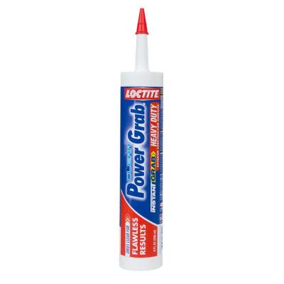
NOTE: After many trials and errors with construction adhesives, I have NEVER FOUND ANYTHING that holds foam to any other substance as well as LOCTITE PowerGrab. I even use it for applying cork roadbed and gluing track (to any surface). It has great tackiness, holds well after just a few minutes and is completely solid after 24 hours.
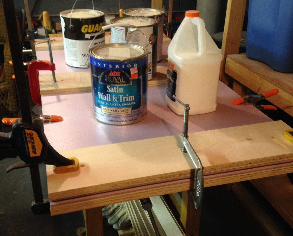
Set the top aside on a flat surface (floor) with as much weight on it as you can (I used paint cans) to dry for 24 hours.
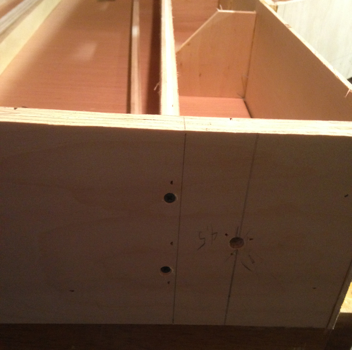
The next step is the frame which consists of the end plates and the side fascias. There are a few details to do before we assemble these pieces. I designed a cart that the finished modules will fit into for easy transport. The end plates will need to have holes drilled for bolts that will hold them steady in the cart. It is best to do these holes now than later. to make sure all the holes are in the same location, I created a simple jig to align and mark the holes.
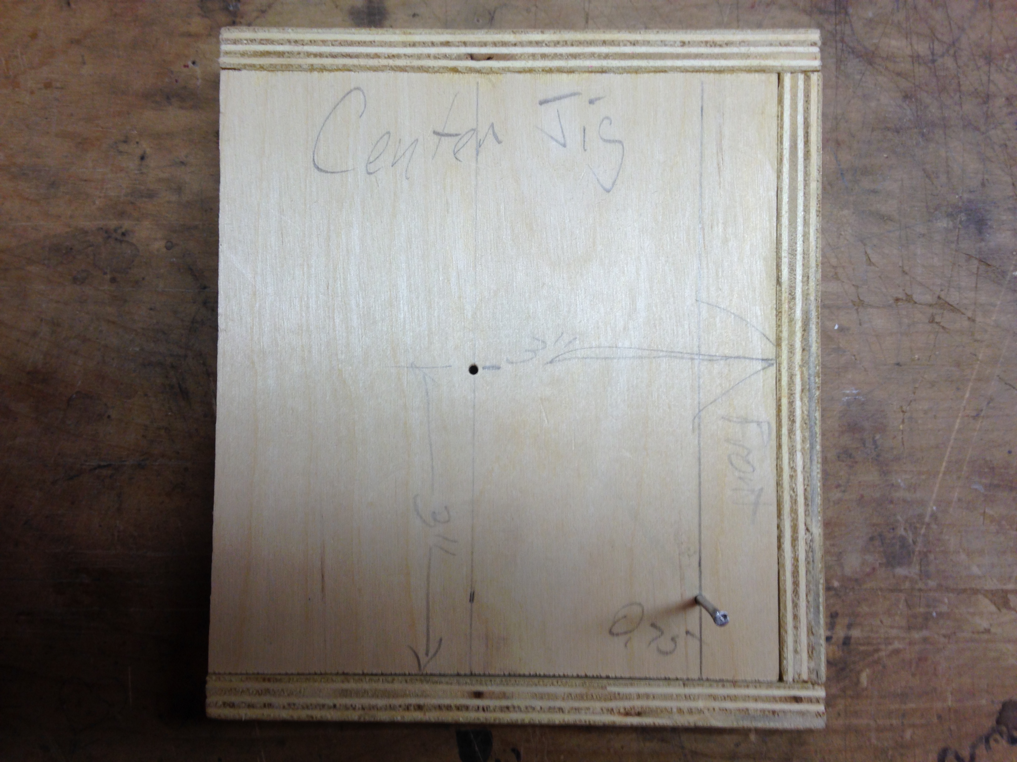
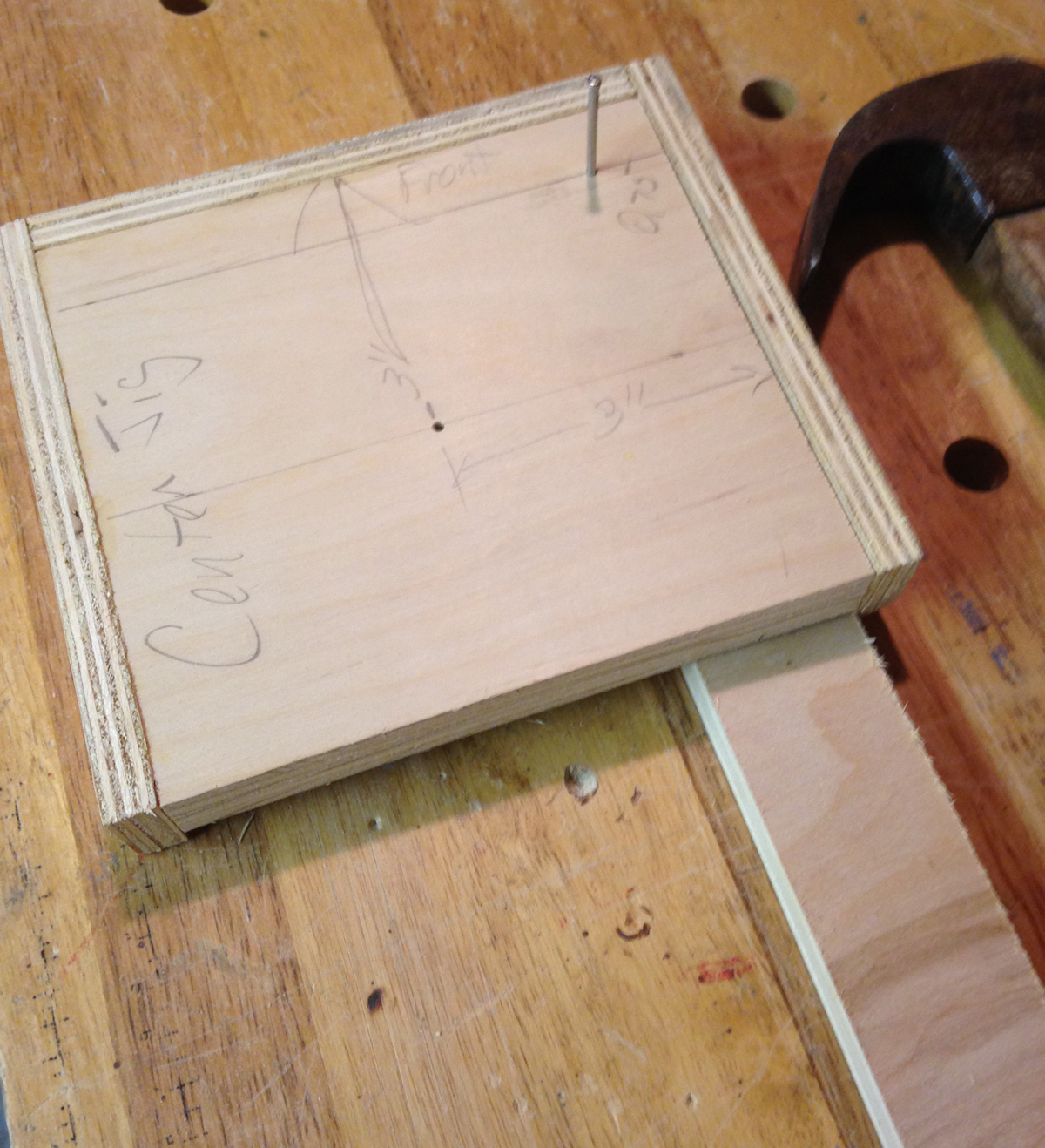
The jig is 6 inches square with trim added on three sides so it fits over the end of an End Cap. in the exact center is a nail which will mark the exact location of the hole I need to drill. This ensures that all alignment holes are in the same location.

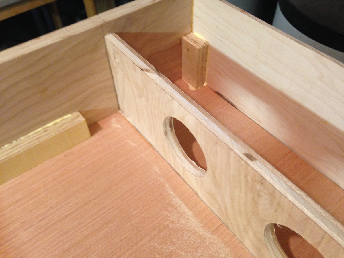
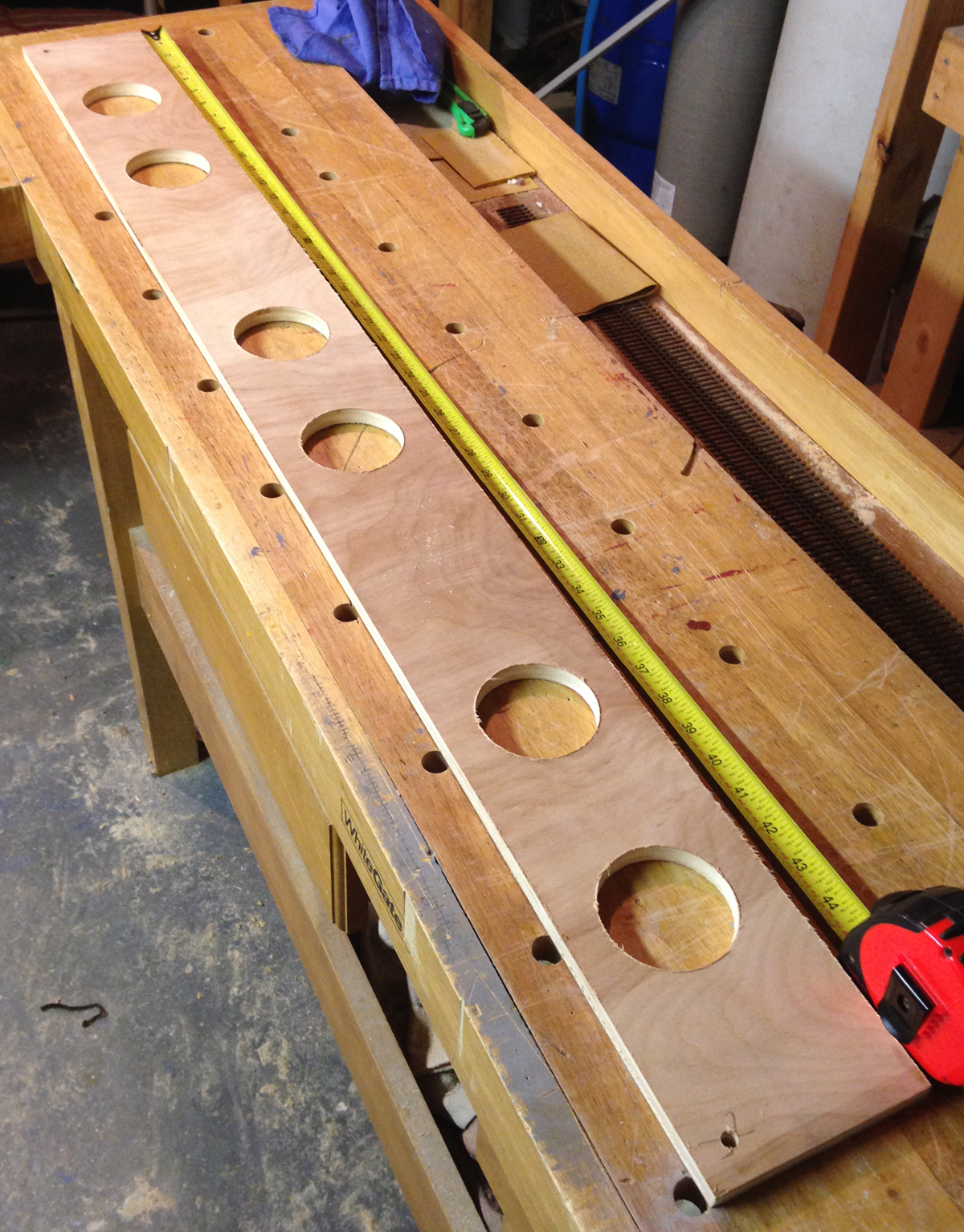
Once the holes are completed in the end plates, mark and cut the holes in the stringers. These holes serve multiple purposes. They lighten the frame and allow wiring to access the outsides of the module.
The bolt holes for the legs need to be drilled into the stringers at this time. They need to be precise so we use our jig again. this time we used a corner of the jig to make a nail hole 2.75″ from the edges at the outside corners.
By now the sandwich should be dry and we can begin actually assembling the frame. The first task is to find a flat surface to assemble everything. if you do not have a workbench like mine, borrow the kitchen floor or some other mostly flat surface (cement floors are not flat).
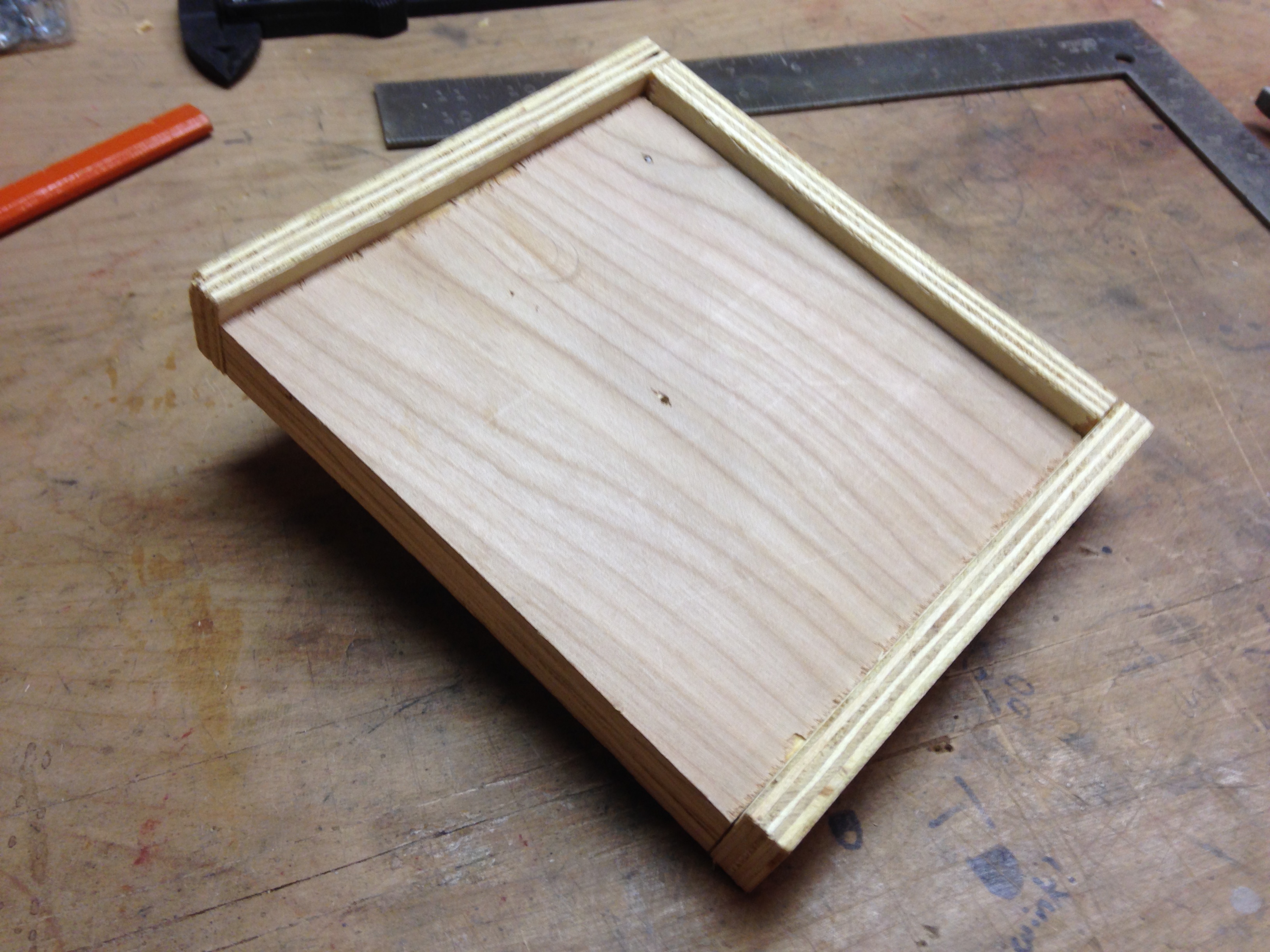
Lay the sandwich foam side down. Check the side measurements to make sure they are NOT wider than 45.5 inches (1/4″ side + 1/4″ + 45.5″ = 46″ width). If the dimensions checkout you should be able to place the end plates and sides against the sandwich and it should all line up and create a box. Again, do not worry about slight gaps on the side but we do not want the width to bulge over 46″ either. If it all fits well, glue (with wood glue) and nail the sides to the end plates. Use the end plates as guides to keep the end plates plum and check with a square as you proceed with each nail.
After the outer frame is assembled mark a line on the sandwich 4.5″ from the inside of the corner on each end. Connect these marks to create a line from end plate to and plate. Place the stringers on this line inside the frame and on top of the sandwich top. It should be snug but not pushing out the ends. Now place some of the gussets in place and check for fit. The side fascias may need to be pulled back in some to meet the gussets. This is the final check on the width of the sandwich. If the sides still bulge due to the width of the top, remove it and make adjustments now with a circular saw or a jig saw.

With the stringers in position (make sure the leg holes are in the correct position), glue and screw the stringers in place. It is important to use screws through the end plates into the stringers. This is THE joint that will receive the most stress when moved.
Next the gussets are added. These to should be glued and screwed to the stringers. Glue and finish nails are used on the fascia side.
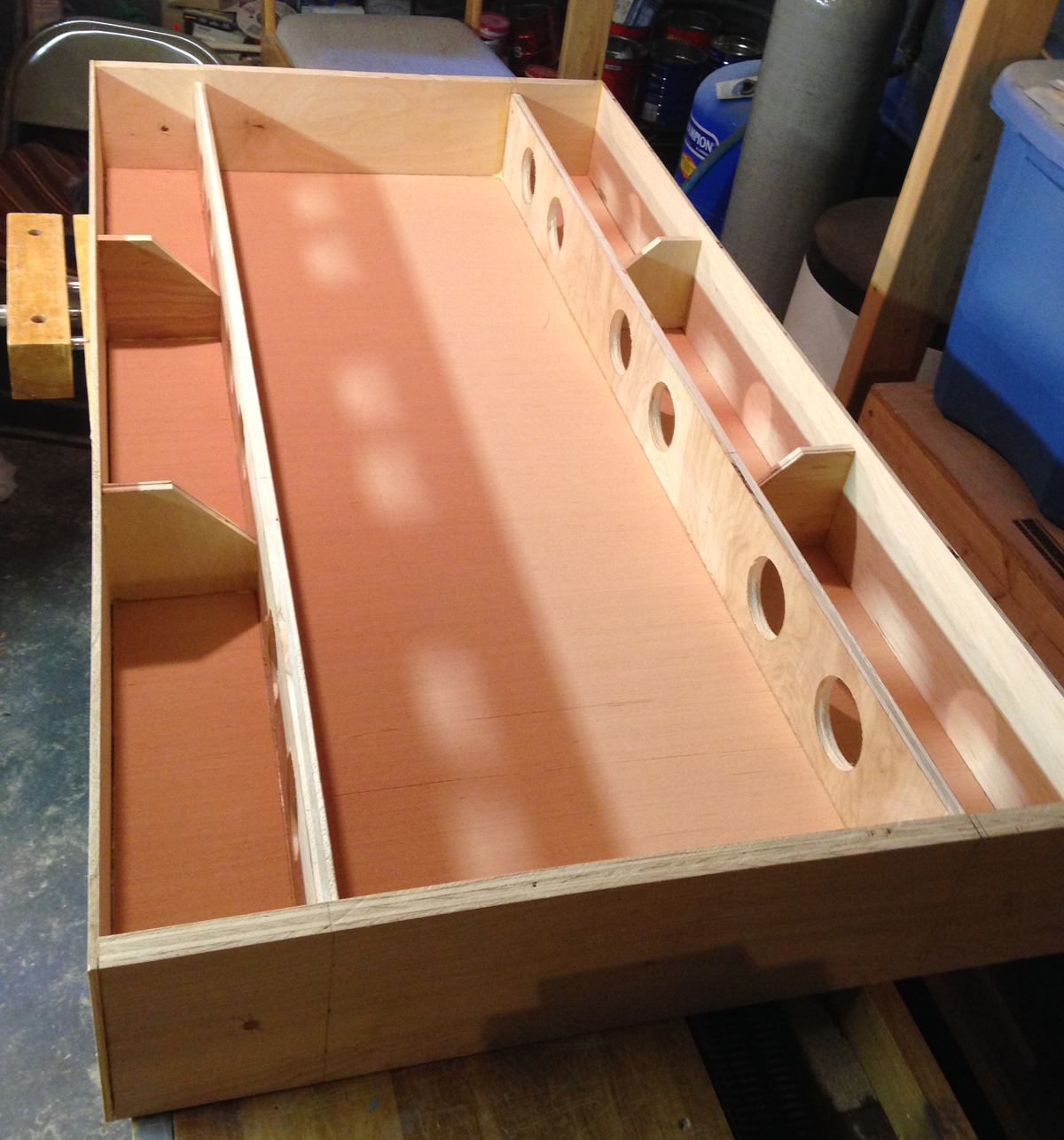
Although the frame is strong at this point, the top has several weak points that require braces. the sizes of these vary and were cut from scrap plywood. Key places to add these reinforcements include were the top meets the end plates, side fascias and in the corners. the exact locations are marked on the Sketchup file available at www.smallmr.com/files/26_wdie_freemo_3.skp.

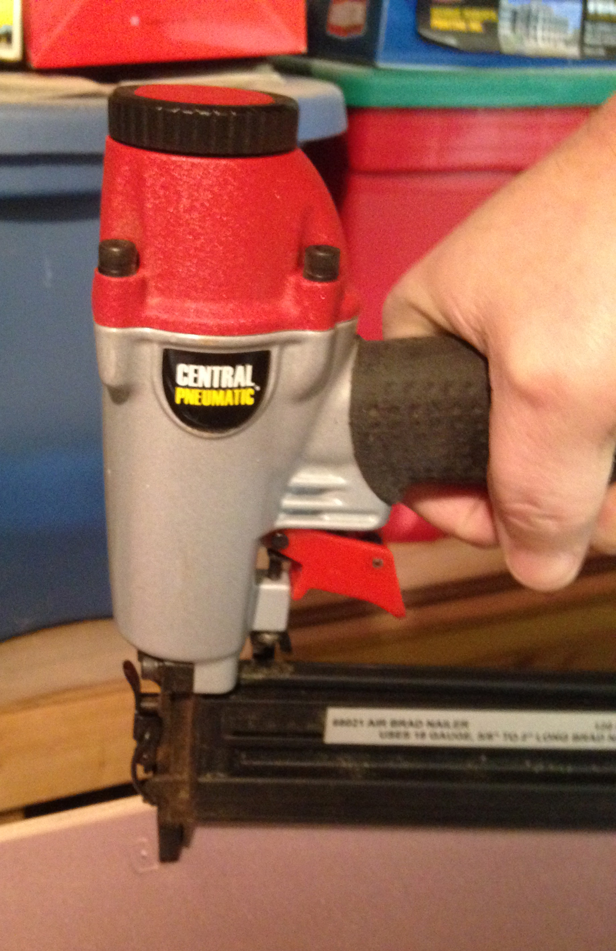
To make sure the top stayed in place while the glue dried, I marked a line on the top to show the location of the stringer underneath. i then used an inexpensive brad nailer to shoot nails through the foam and plywood top and secure it to the stringer.
When the bracing is completed, it is a good idea to take a sanding block to all edges of the plywood frame. this helps to cut down on the sharp edges and splinters that could be hiding.

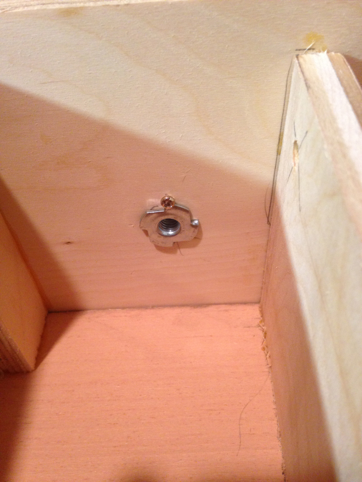
Tee Nuts are added to the inside of the end plates and secured in position with small screws. I always seem to loose Tee Nuts if they are not secured in this way. Bolts in the cart hold the module in position.
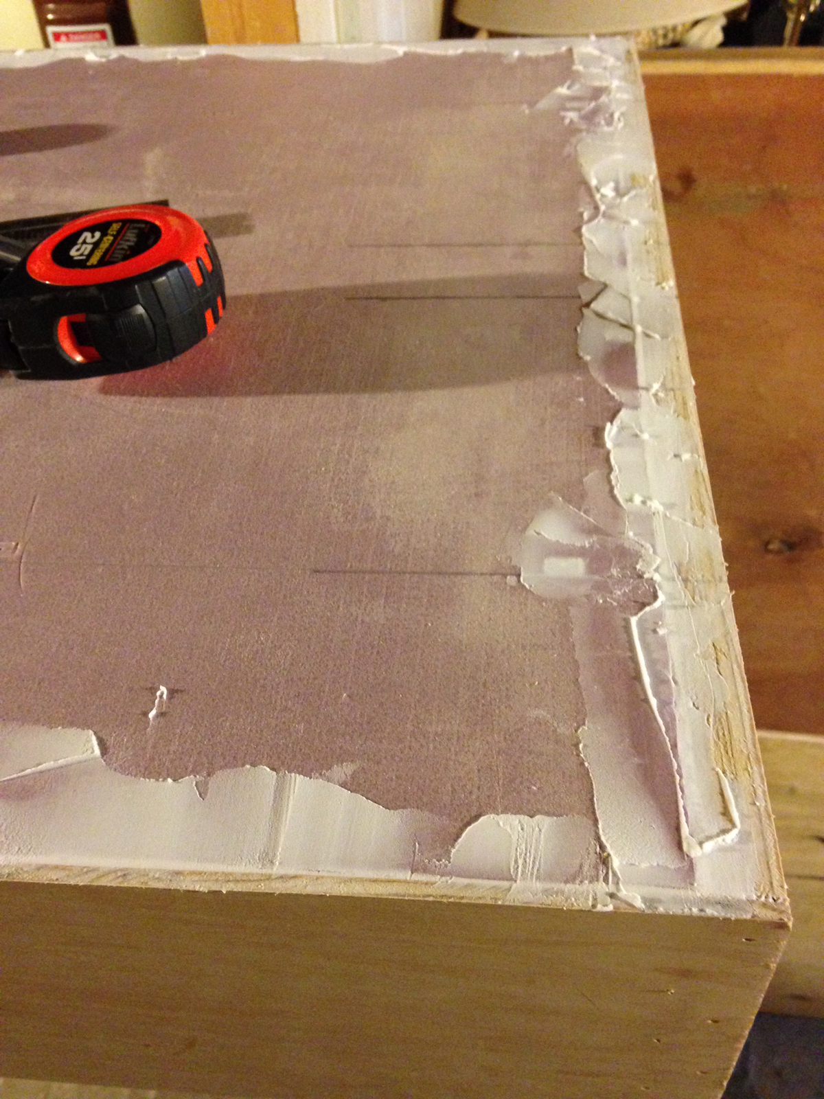
Once the frame is complete, I use premixed light weight vinyl spackle to fill all voids around the edges. This spackle has some give in it so it will not crack and separate as easily as traditional spackle. Allow the spackle to dry and sand it smooth.
I think that is enough for now. In the next installment, we will assemble the legs that fold up into the frame.