With the building of my new Free-mo module set “The Boat Yard“, I have had to change some of my usual “go to” items. I have always used Tortoise turnout motors in the past. These have been great performers that took little time to set up and they had built it frog polarity circuits. The issue with using them in the Boat Yard was purely financial. I needed over 20 of them to complete the project, and at $15-$20 each, it was really hurting the budget.
I decided to take a look at RC Servos. I quickly discovered that the servos themselves were not very expensive. I purchased 10 for $18.00 (less than $2 each) but I still lacked a way to operate them. Servos require a “controller” of some type to generate a signal that tells the servo which way to turn and how much to turn.
For those without knowledge of how a servo works here is a very quick and dirty “How It Works”:
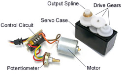
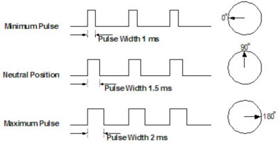
Servos have three wires, Positive, negative and Control. They are controlled by sending an electrical pulse of variable width, or pulse width modulation (PWM), through the control wire. There is a minimum pulse, a maximum pulse, and a repetition rate. A servo motor can usually only turn 90 degrees in either direction for a total of 180 degree movement. The motor’s neutral position is defined as the position where the servo has the same amount of potential rotation in the both the clockwise or counter-clockwise direction (that was a lot of geek speak to say “center”). The PWM sent to the motor determines position of the shaft, and based on the duration of the pulse sent via the control wire; the rotor will turn to the desired position. The servo motor expects to see a pulse every 20 milliseconds (ms) and the length of the pulse will determine how far the motor turns. For example, a 1.5ms pulse will make the motor turn to the 90-degree position. Shorter than 1.5ms moves it to 0 degrees, and any longer than 1.5ms will turn the servo to 180 degrees.
A servo cannot operate by just adding power like a motor. It requires a controller circuit to send the PWM signal to tell it what to do. In turn you have to tell the controller circuit what you want with a switch or other electrical signal.
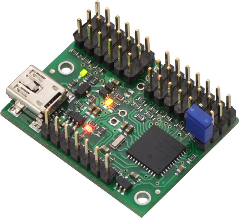
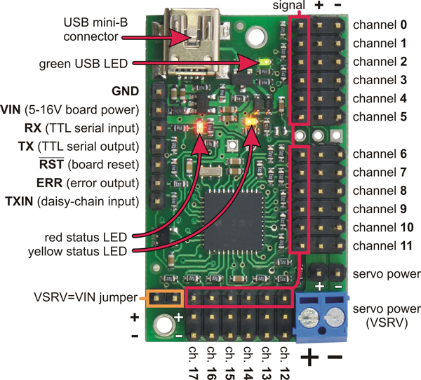
There are a few makers of servo controllers for the model train market including Tam Valley, MegaPoints and a servo driving kit from the Model Electric Railway Group (MERG). Each has its benefits and liabilities. By searching a little deeper I found a series of servo controller boards from Pololu called the Mini Maestro which had a very low price and afforded the flexibility I required. They come in 6, 12, 18 and 24 channel versions, allowing you to buy only as much controller as you need.

The Mini Maestros have a USB interface so they can attach to a computer/laptop. Servos can be run either directly from the downloaded Pololu software or a script can be loaded into the Maestro for automation. This allows me to adjust the characteristics of the board or tweak the program at any time.
The Maestro can be configured for automation of servo control, with inputs, outputs or both. The Boat Yard contains a double crossover and an interchange that should have an interlock. With the Mini Maestro I can program the actions of the interlock directly into the board and control it with a couple toggle switches on the fascia.
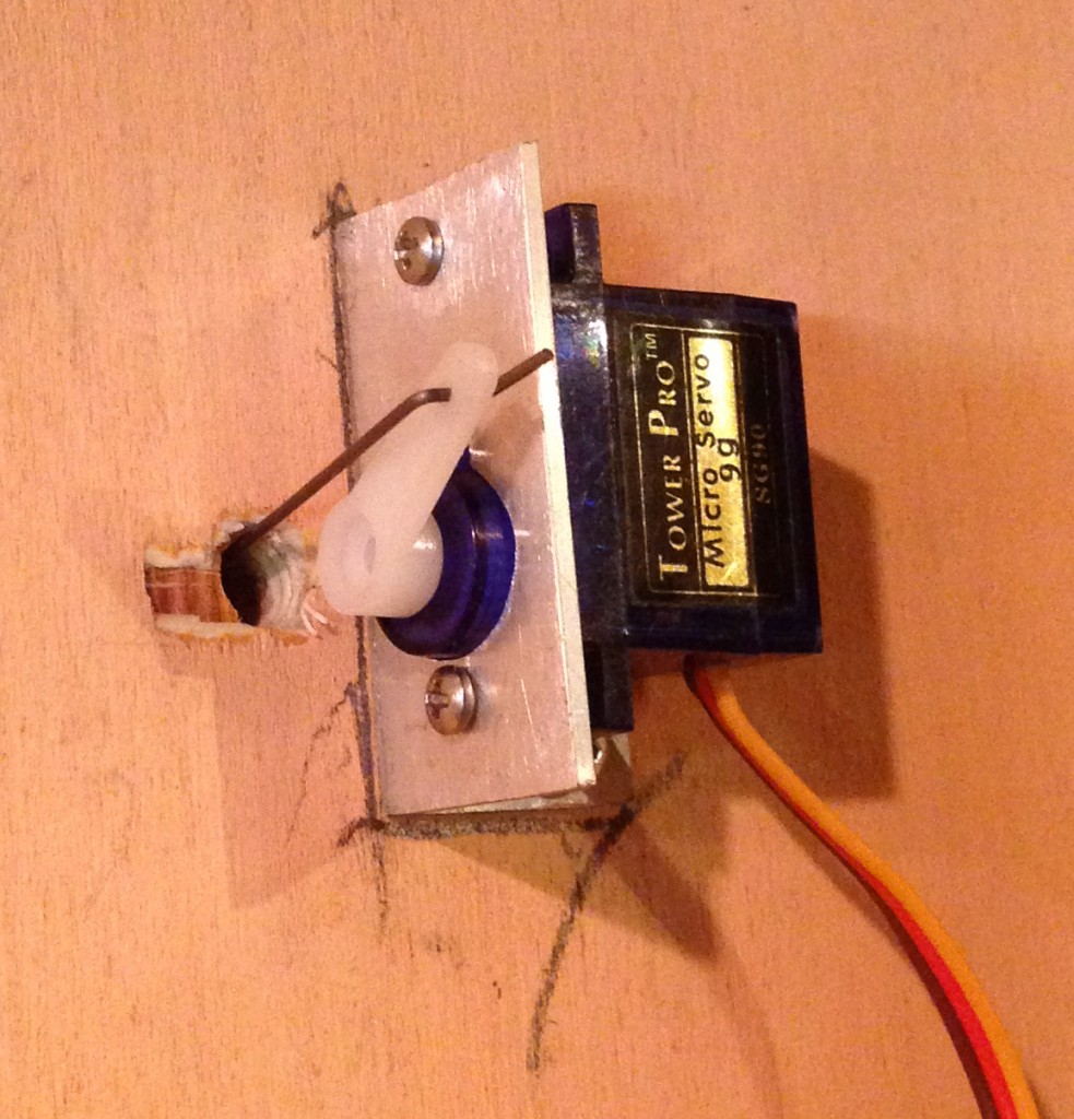
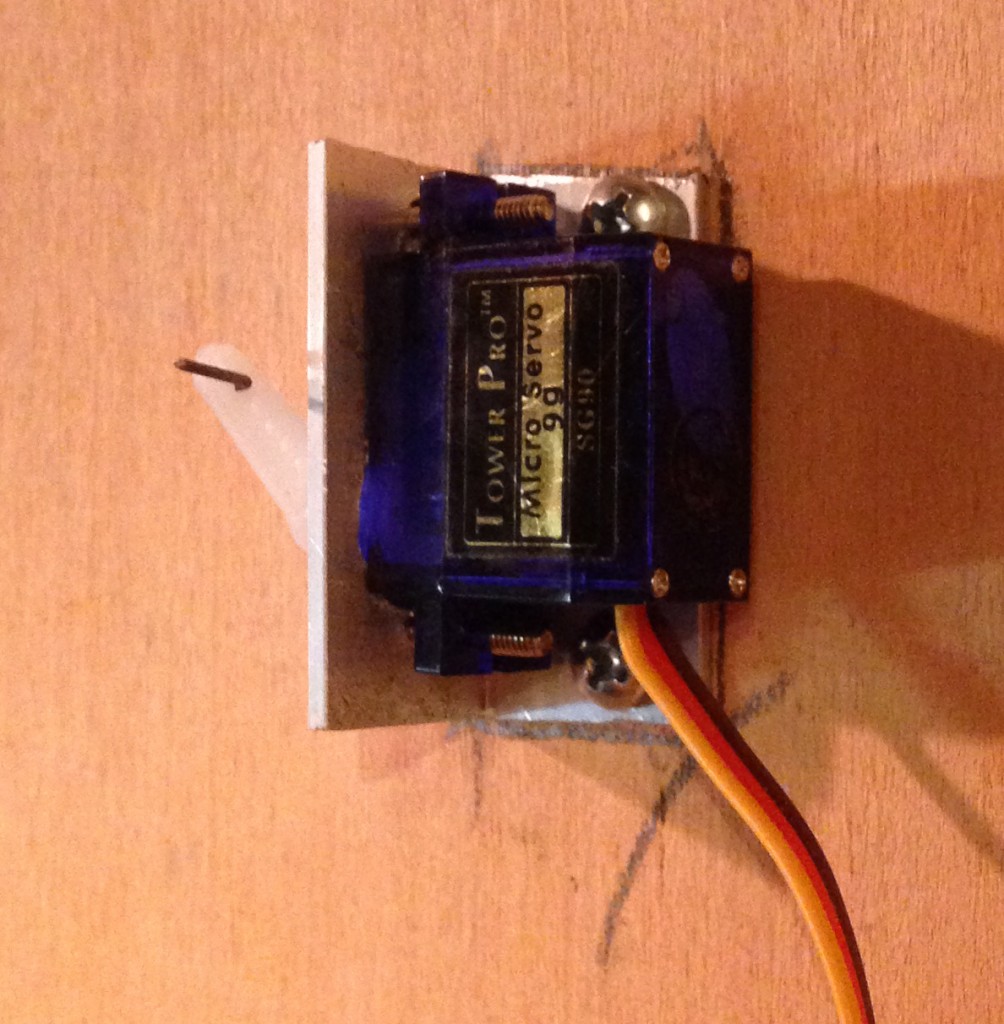
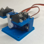
The last issue was how to mount the servos. After much deliberation I was able to determine that the module design I was using allowed me to use the plywood top as a fulcrum for the servos. The distance from the turnout to the plywood was just right. See my other article on free-mo module Design. With this knowledge I acquired a piece of 3/4 inch angle aluminum and cut it into 1.5″ in lengths.
After carefully measuring a servo, I created a template in Adobe illustrator to locate the holes required to mount the servo.
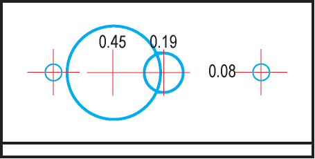
The template is affixed to the aluminum angle with spray glue and the holes drilled out. The servo then mounts with two small screws and uses the same piano wire that would have been used on a Tortoise. The end must be bent into an “S” configuration to hold position in the servo arm.
Sample Wiring and Code
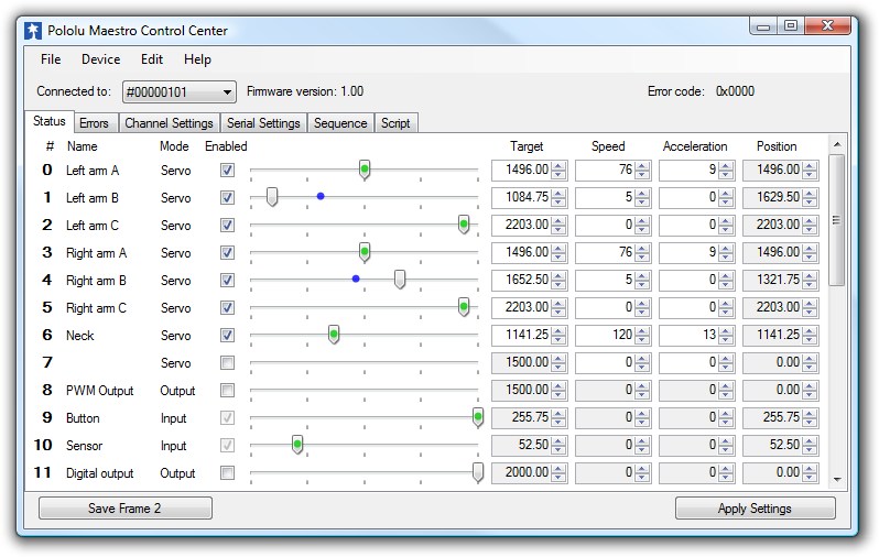
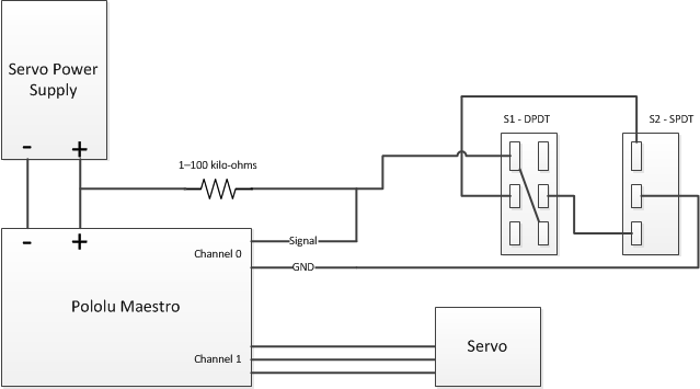
The following wiring and code uses Channel 0 on the Maestro as an input and Channel 1 as a servo. These need to be configured in the Pololu Maestro Control Center BEFORE using the wiring diagram and the sample code provided or damage may occur.
Free-mo requires that all turnouts have controls on each side of the layout. I typically do this with toggle switches on each side. The wiring for this with a Tortoise is well documented. With the Maestro however you need to do things a little different. You could setup two inputs on the Maestro and create code to react when ever either input changes state. this might seem the way to go but I would tie up a lot of channels with this method. Instead I used a hybrid of the Tortoise wiring. Only the negative signal needs to be carried so I use a DPDT toggle for one side of the module and a SPDT on the other (or half of a DPDT). The following diagram shows how this works. You will need to set Channel 0 as an input and upload the appropriate code.
The following is the code to make the Maestro operate a single turnout in conjunction with the diagram above. Before using the code the correct values for the servo positions must be obtained. You can do this by connecting the Maestro to your computer and running using the Pololu Maestro Control Center to manually operate the servo. Note the values for each position. The value entered in the code is 4X the value shown in the status tab.
# When the script is not doing anything else,
# this loop will listen for switch position change.
# When a switch is thrown it runs the corresponding sequence.
begin
input_0 if sequence_a else sequence_b endif
repeat
# These subroutines each return 1 if the corresponding
# switch is thrown, and return 0 otherwise.
# Currently switch input is assigned to channel 0,
# This channel must be configured as Input in the
# Channel Settings tab.
sub input_0
0 get_position 500 less_than
return
# These subroutines each perform a servo movement.
# You should change these to fit your application.
# Value used is 4X the value shown in the status tab
sub sequence_a
4000 1 servo
return
sub sequence_b
8000 1 servo
return
Next time I will review how I powered the frogs. Currently the plan is to use inexpensive low voltage relays but if that fails a SPDT micro switch may be required.
Oh, neat. I’ve been looking at Tam Valley for a long time. Right now I just use ground throws. But the Pololu items look interesting. I’ll definitely look more into this as I have a bunch of servos laying around begging to be used. Thanks for this post.
Glad you like it. I am still working on the integration for frog powering via an inexpensive relay or latching circuit. I should be done with testing and have more on that in the next two weeks.
We use Tam Valley Depot they are a great product . We like them cause of the loconet that is on the board. And we can run up to 8 servos single or 16 double ! Also they offer the signal board that is a attachment !
But we also have them on the North Metro Model Railroad Club!
I agree, Tam Valley Depot has a great product. The article is NOT intended to say that Tam Valley Depot or any other product is sub-standard to the Maestro controller. It is simply another option with unique abilities. The single feature that turned me on to this controller over the others was the ability to setup complex route control and to be able to create an interlock. I am hoping to do further articles on these advanced concepts in the near future.
I agree that the maestro has strong possibilities for route control, etc. The cost per switch machine is much lower than other options. The only drawback I found reading up about the maestro is that the software program does not multitask easily. (In other words if you push button A to operate turnout A the software will not recognize other pushbuttons until turnout A servo has completed the movement programmed into the software.) Multitasking can be done, but it takes more code to make it work. After searching the net I found this article on the maestro forum on how to multitask the software. It walks you through multitasking 2 buttons operating 2 servos. It can be expanded for more that 2 buttons and servos depending on your needs and requirements. Enjoy!https://forum.pololu.com/t/mini-maestro-24-with-multiple-buttons/6259
The Maestro is not for everyone, especially if code intimidates you. I am very comfortable with the code and had already defined some complex code for other applications.
The cost is not as straight forward. Just because you have 12 servo outputs does not mean that you can use 12 servos. If you need to define an input, you just lost one of the servo outputs. If you use 1 input for each servo, you just cut the number of servos you can run to 6. That is a lot less cost efficient. The Maestro (IMHO) is best for complicated turnout configurations or where more flexibility is required. As stated before, it is just another option out there.
Hello. I just stumbled on this site. Everything I have questions about, are answered here. I may try servos for the same cost reason. Didn’t see how you wire a servo that, for example, is 8 feet away. Can I buy the plugs, with wires attached, and simply extend the wires. I know next to nothing about servos. Thank you.
You can get extension cables for servos but eight feet I think is too long. Are you trying to use one control board and one is that far from the others? You might want to consider a Tam Valley Micro Singlet Servo Decoder Board (http://www.tamvalleydepot.com/products/microsinglet.html) just for that far away servo.
I’m interested in this topic too. I’m looking at using the Arduino boards and writing the code needed to get things to work. Very simple code but should not be all that difficult to do. Interested seeing the updates in regards to your transport troubles also.
Regards
Any new developments? Certainly, the proposed 2-weeks before the next segments have passed…..
Sorry for not getting the next phase of this topic completed. The servo saga is continuing to this day. I did the servos and relays which at first worked great. After three setups I have noted some issues with the electronics and continued chatter on the servos. I have not done a new article yet as i have not resolved the issues. They can be resolved but some life changes have gotten in the way. I will be continuing the article including how i am using 3D printing to make better servo mounts.
I am using a Tam Valley board, but it controls a little less than half of the servos I want to use. What is the cost af the other boards and who makes them?
Doug
The Pololu Maestro boards run between $19.95 (6 servos) and $47.95 (24 servos). They have several sizes to choose from. You can order them direct at https://www.pololu.com/category/102/maestro-usb-servo-controllers. The Pololu require more effort on the programming but will also allow more flexibility. I have a follow-up article to this one coming up. After a few years of using servos, I have developed a few extra tips to make things work better.
Marshall,
Thanks. The reason I am using sernos (top mounted 9g) is the I am disabled with MS and cannot get under my layout. Besides they are much cheaper than Tortoises and cheaper too.
Doug
I am just getting into MR again after 50 yr hiatus. Settled on a track plan and realized I have over 50 turnouts to throw…”Turtles” are NOT going to be used, I’ll guarantee you that since they now cost $19.00 plus tax + S&H + $3.00 for a wire interface!!! WTF? IT has no way to connect a frikkin wire w/o paying MORE? BS, I am not biting.
Cheapest servos are $1.00 each in quantities, I’ve already found all you need to do to mount them is use a little piece of 5/8″ x 5/8″ aluminum “trim” channel available at Home Depot just $10.00 for 8 FEET of the stuff. Screw 1/2″ of it to the plywood, slip in the SR90 or SR92R servo and away ya go. If the fit is sloppy, line the thing with “hockey tape”, also known as friction tape also available at local hardware stores.
I bought my first servo with a tiny circuit board already inside. You apply power momentarily and it turns 90° right, from dead center. Reverse polarity and apply momentary power and it turns 180° opposite way. No Arduino, no expensive control boards, no fooling around with code…yeah, how much easier can it get? How much cheaper? That Servo cost $2.50, free shipping, ordered from China off eBay and waited 5 weeks.
This is rally clever. A lot of guys on the hustle forget that the main reason of going to servos is to be on the cheap. To end up spending like $10-$20 for a servo+mount set up, you may as well go to Walthers. Thanks!